Difference between revisions of "Sensor-PIR"

From Microduino Wiki
Jump to: navigation, search
(Document)
 
(4 intermediate revisions by 2 users not shown)
Line 11: Line 11:
  
 
==Introduction of Pins==
 
==Introduction of Pins==
{{Sensor_explain
+
{{ST_Pinout
|nameA=[[Sensor-PIR]]
+
|st_name=PIR Sensor
|modeA=Digital read
+
|pin3=Digital Input
|modeB=NC
 
 
}}
 
}}


==Features==
 
==Features==
Line 35: Line 33:
 
*Size
 
*Size
 
**Size of the board: 23.5mm*13mm
 
**Size of the board: 23.5mm*13mm
**1.27mm-spacing 4Pin itnerface connected to sensorhub
+
**1.27mm-spacing 4Pin interface connected to sensorhub
 
**The CAD drawing of the sensor: '''[[File:Sensor_CAD.zip]]'''
 
**The CAD drawing of the sensor: '''[[File:Sensor_CAD.zip]]'''
 
*Technical parameters  
 
*Technical parameters  
Line 50: Line 48:
  
 
==Development==
 
==Development==
===Equipment===
+
===Program Download===
{|class="wikitable"
+
*Download and unzip the program '''[[File:Sensor-PIR_Test.zip]]'''
|-
 
|Module||Number||Function
 
|-
 
|[[mCookie-CoreUSB]]||1||Core board
 
|-
 
|[[mCookie-Hub]]||1||Sensor pin board
 
|-
 
|[[Microduino-PIR]]||1||Pyroelectric infrared sensor
 
|}
 
  
*Other hardware equipment
+
===Programming===
**One USB cable
+
{{Upload
[[File:Passive Infrared.jpg|600px|center]]
+
|nameA=[[Microduino-Core]], [[Microduino-USBTTL]]
 
+
|nameB=[[Microduino-USBTTL]]
===Preparation===
+
|boardName=Microduino/mCookie-Core(328p), Atmega328P@16M,5V
*Setup 1: Connect the PIR to the D6 of the Hub.
+
|fileName=Sensor-PIR Test.ino
[[file:mCookie-Passive Infrared-sensor.JPG|600px|center]]
+
}}
*Setup 2: Assemble the CoreUSB, Hub and the PIR together, then connect them to the computer.
 
[[file:mCookie-pir-pc.JPG|600px|center]]


===Experiment: Detect If there is person moving ===
 
*Open Arduino IDE and copy the following codes into IDE.  
 
<source lang="cpp">
 
#define  sensorPin  6


int state;
 
  
void setup()
+
===Hardware Setup===
{
+
*Referring to the following diagram, connect the Sensor-PIR to the digital pin D6 of '''[[Microduino-Sensorhub]]'''.
  pinMode(sensorPin, INPUT);
+
<br>
  Serial.begin(9600);
+
[[file:Microduino-sensorhub_Crash.JPG|thumb|400px|left]]
}
+
<br style="clear: left"/>
void loop()
 
{
 
  state = digitalRead(sensorPin);
 
  if (state == 1)
 
    Serial.println("Somebody is in this area!");
 
  else
 
    Serial.println("No one!");
 
  delay(500);
 
}
 
</source>
 
*Select the right port in (Tools)→(Serial Port)under Arduino IDE.
 
[[file:upload.JPG|600px|center]]
 
*Compile and then download the program. 
 
[[file:upload-pir.JPG|600px|center]]
 
*After the download, you can open the serial monitor. The displayed notice reflects the status detected by the current sensor.
 
[[file:mCookie-pir-res.JPG|600px|center]]
 
*Result
 
When the PIR is detecting the moving persons, it'll output high level in the output pin, which is 5V. And when it detected the PIR signal gone, it'll output low level(0V) after 2.3-3s delay. Therefore, we can according to that to establish a moving person detection project according to that. 
 
  
===Program Debugging===
+
===Result===
*"#define  sensorPin  6" defines sensor interface.    
+
*After download, open the serial monitor.  
*Use "" digitalRead(sensorPin); to read sensor change and to judge if there is moving human body.
+
*The static sensor signal is LOW. After detect the IR emitted by living things within measurement range, it changes into HIGH.
  
 
==Application==
 
==Application==
Line 115: Line 77:


==Purchase==


==History==
 
==History==
  
==Image==
+
==Gallery==
 
+
{| border="0" cellpadding="10" width="100%"
*Front
+
|-
[[file: Microduino-Passive Infrared-F.JPG|thumb|600px|center|Microduino-Passive Infrared Front]]
+
|width="50%" valign="top" align="left"|
*Back
+
[[file: Microduino-Passive Infrared-F1.JPG|thumb|400px|center|Sensor-PIR Front]]
[[file: Microduino-Passive Infrared-b.JPG|thumb|600px|center|Microduino-Passive Infrared Back]]
+
|width="50%" valign="top" align="left"|
 +
[[file: Microduino-Passive Infrared-b1.JPG|thumb|400px|center|Sensor-PIR Back]]
 +
|}
 
|}
 
|}

Latest revision as of 06:57, 4 August 2017

Language: English  • 中文
Sensor-PIR

The product number of Sensor-PIR is: MSDI51

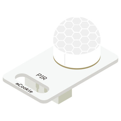
Sensor-PIR is a pyroelectric infrared sensor that can detect infrared rays sent from moving human body or animals. It can output switch signals and be used in various occasions that need to detect moving human body.


Introduction of Pins

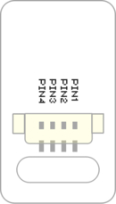
Sensor backpin.png

PIR Sensor
General Pin Out Sensor / Trinket's Pin Out
PIN1 (GND) GND
PIN2 (VCC) VCC
PIN3 (SIGNAL-A) Digital Input
PIN4 (SIGNAL-B) Not Connected
  • General Pin Out is the standard pin out of a Sensor / Trinket connector.
  • Sensor / Trinket's Pin Out is this specific Sensor / Trinket's wiring in relation to the General Pin Out.
  • SIGNAL-A / SIGNAL-B are signals that could be digital input, digital output, analog input or analog output. Or special signals such as serial communication (SoftwareSerial, IIC (I2C), etc) or other special signals.
  • Not Connected refers to the Pin not being used for this particular Sensor / Trinket.
  • Read more about the hub module.

Features

  • Adopt digital integrated pyroelectric infrared probe AM412.
  • With high precision and sensitivity.
  • Low power consumption, long service life and good stability.
  • Digital signals
  • Small size and easy to install.

Specification

  • Voltage
    • 3.3V~5V working voltage
  • Electrical specification
    • Working current: 15uA
    • Working temperature: -20~85℃
    • Output voltage: high level 5V, low level 0V
  • Size
    • Size of the board: 23.5mm*13mm
    • 1.27mm-spacing 4Pin interface connected to sensorhub
    • The CAD drawing of the sensor: File:Sensor CAD.zip
  • Technical parameters
    • Output delay(high level): about 2.3~3s
    • Induction angle: 100°
    • Induction distance: 7m
  • Connection
    • This sensor can be connected to the following interfaces of core: D2~D13,A0~A7

Document

Development

Program Download

Programming

  • Follow the Software Getting Started Guide.
  • Select the Board, Processor and Port.
  • Click [File]->[Open], browse to the project program address, and click "Sensor-PIR Test.ino" to open the program.
  • After confirming all these items are correct, click "→" to download the program to the development board.

Hardware Setup

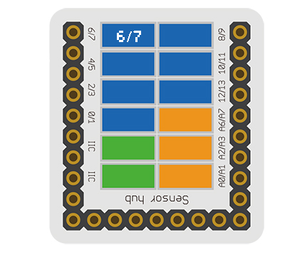
  • Referring to the following diagram, connect the Sensor-PIR to the digital pin D6 of Microduino-Sensorhub.


Microduino-sensorhub Crash.JPG


Result

  • After download, open the serial monitor.
  • The static sensor signal is LOW. After detect the IR emitted by living things within measurement range, it changes into HIGH.

Application

  • Intrusion alarm
  • Non-contact infrared automatic switch


Project

History

Gallery

Retrieved from "https://wiki.microduinoinc.com/index.php?title=Sensor-PIR&oldid=21502"