Difference between revisions of "Microphone Sound Detection"
From Microduino Wiki
(Created page with "{| style="width: 800px;" |- | =Function of the Module= *'''Please refer to: Sound Detection Sensor''' *As an analog input sensor, the values it detect have a certain range...") |
|||
| Line 25: | Line 25: | ||
==Hardware Buildup== | ==Hardware Buildup== | ||
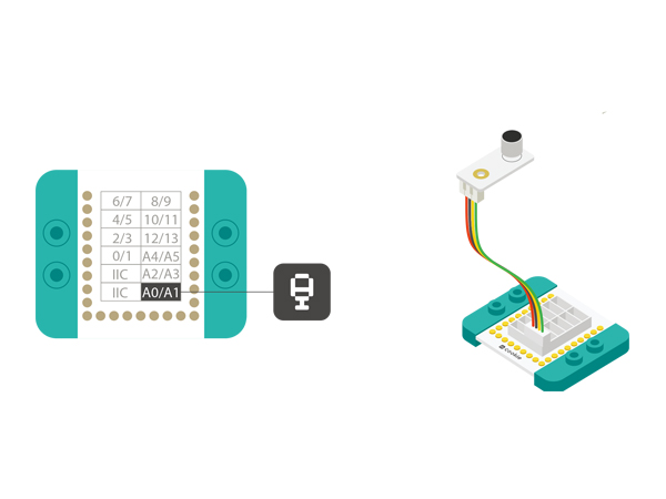
| − | *Setup | + | *Setup 1: Connect the MIC sensor with the A0 analog port of the Hub, which is the control pin of the MIC. Therefore, MIC is an analog sensor. Users can change the analog port to A2 or A4 on your own. |
[[file:mCookie-Sound-sensor.JPG|600px|center]] | [[file:mCookie-Sound-sensor.JPG|600px|center]] | ||
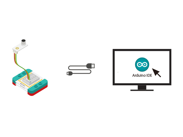
| − | *Setup | + | *Setup 2: Connect the CoreUSB, Hub and the Sound sensor to the computer with a USB cable. |
[[file:mCookie-Sound-pc.JPG|600px|center]] | [[file:mCookie-Sound-pc.JPG|600px|center]] | ||
==Mixly Programming== | ==Mixly Programming== | ||
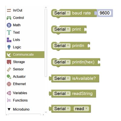
| − | * | + | *Step1: Since using serial monitor, we need to find "Serial Communication" from "Communication" item. |
[[File:mixly_Serial.jpg|400px|center]] | [[File:mixly_Serial.jpg|400px|center]] | ||
| − | * | + | *Step2: "Serial Communication" description. |
[[File:mixly_Serial_complian.jpg|600px|center]] | [[File:mixly_Serial_complian.jpg|600px|center]] | ||
| − | * | + | *Step3: MIC sound sensor is an input device and the value of the sound has a certain range while the returned data is digital quantity, based on which we can find and drag out the digital input and output from "Input/Output". |
[[File:mixly_in-out.jpg|600px|center]] | [[File:mixly_in-out.jpg|600px|center]] | ||
*"Analog Input" description. | *"Analog Input" description. | ||
| Line 42: | Line 42: | ||
[[File:mixly_analog-in-serial.jpg|600px|center]] | [[File:mixly_analog-in-serial.jpg|600px|center]] | ||
==Debugging== | ==Debugging== | ||
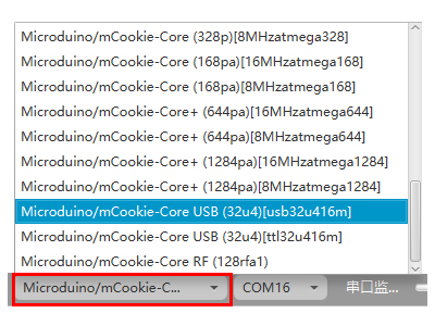
| − | * | + | *Step1: Select the right board card(Core USB 32U4) and COM port(Recognized automatically by default). |
[[File:mixly_board_COM.jpg|400px|center]] | [[File:mixly_board_COM.jpg|400px|center]] | ||
| − | * | + | *Step2: Open the serial monitor. |
[[File:mixly_COMXX.jpg|400px|center]] | [[File:mixly_COMXX.jpg|400px|center]] | ||
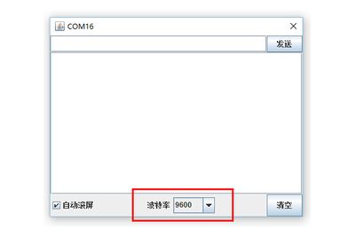
| − | * | + | *Step3: Check if the serial baud rate is the same with the pre-set one. |
[[File:mixly_COMXX_ok.jpg|400px|center]] | [[File:mixly_COMXX_ok.jpg|400px|center]] | ||
| − | * | + | *Step4: Check the data and you'll find: When there is no sound around the sensor, the data is about 10. And the data is getting bigger along with the sound becoming louder, the maximum is about 700. |
[[File:mixly_COMXX_data—mic.jpg|400px|center]] | [[File:mixly_COMXX_data—mic.jpg|400px|center]] | ||
Latest revision as of 09:46, 13 September 2016
ContentsFunction of the Module
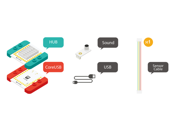
OverviewTo use the sound/microphone(MIC) sensor to detect sound and check data in the serial monitor. Bill of Material
Hardware Buildup
Mixly Programming
Debugging
Extension
|
