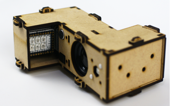
Difference between revisions of "Open Source Voice Scene Light"
(Created page with "{| style="width: 800px;" |- | ==Outline== *Project:Microduino open source voice scene light *Objective:Control various bright lights method through voice. *Difficulty:Me...") |
|||
| (4 intermediate revisions by 2 users not shown) | |||
| Line 3: | Line 3: | ||
| | | | ||
==Outline== | ==Outline== | ||
| − | * | + | *Project: Microduino open source voice scene light |
| − | * | + | *Objective: Control various bright lights method through voice. |
| − | * | + | *Difficulty: Medium |
| − | *Time- | + | *Time-consuming: 2 hours |
| − | * | + | *Maker: |
*Introduction: | *Introduction: | ||
| − | In this tutorial, we will use Microduino product module to quickly set up alighting control | + | In this tutorial, we will use Microduino product module to quickly set up alighting control system which can identify the human's voice. The player can quickly start, and can control the on and off of the light module and choose color through speaking. |
==Bill of Material== | ==Bill of Material== | ||
| Line 33: | Line 33: | ||
|[[Microduino-Temp&Hum]] ||1||The temperature and humidity sensors | |[[Microduino-Temp&Hum]] ||1||The temperature and humidity sensors | ||
|- | |- | ||
| − | |[[Microduino-Color | + | |[[Microduino-Color LED]]||1||Voice input instruction |
|} | |} | ||
| − | * | + | *Other Equipment |
{|class="wikitable" | {|class="wikitable" | ||
|- | |- | ||
| Line 57: | Line 57: | ||
*[[Microduino-Temp&Hum]] | *[[Microduino-Temp&Hum]] | ||
The suite use Microduino-Lamp module as light-emitting device, which connect 6 RGB3 colored lights, and can use the corresponding library functions to control the color of every lights. In order to clearly illustrate lights control method, we take a simple program as example. | The suite use Microduino-Lamp module as light-emitting device, which connect 6 RGB3 colored lights, and can use the corresponding library functions to control the color of every lights. In order to clearly illustrate lights control method, we take a simple program as example. | ||
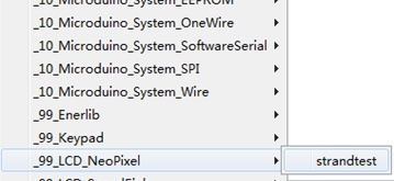
| − | Open Arduino IDE, under the root(File)—>(Examples)—>_99_LCD_NeoPixel, click and open the routine | + | Open Arduino IDE, under the root(File)—>(Examples)—>_99_LCD_NeoPixel, click and open the routine strand test. |
[[File:Emotionlightlib.jpg||600px|center]] | [[File:Emotionlightlib.jpg||600px|center]] | ||
<source lang="cpp"> | <source lang="cpp"> | ||
| Line 84: | Line 84: | ||
rainbowCycle(20); | rainbowCycle(20); | ||
} | } | ||
| − | //Use the color the | + | //Use the color the "c" represents lit the lamp lights in turn, and every time light a lamp wait "wait" seconds. |
void colorWipe(uint32_t c, uint8_t wait) | void colorWipe(uint32_t c, uint8_t wait) | ||
{ | { | ||
for(uint16_t i = 0; i < strip.numPixels(); i++) //Light in turn. | for(uint16_t i = 0; i < strip.numPixels(); i++) //Light in turn. | ||
{ | { | ||
| − | strip.setPixelColor(i, c); //This function is used to light the number i lamp with the | + | strip.setPixelColor(i, c); //This function is used to light the number i lamp with the color"c" represents. |
strip.show(); //This function will display the control information which the setPixelColor function writes. | strip.show(); //This function will display the control information which the setPixelColor function writes. | ||
//Come out, on which is lighted lamp module. | //Come out, on which is lighted lamp module. | ||
| Line 148: | Line 148: | ||
==Document== | ==Document== | ||
| − | The code of the voice scenario | + | The code of the voice scenario light: ['''[[media:EGGROOM.zip|Code to download]]'''] |
| − | The voice scene light sound | + | The voice scene light sound file: ['''[[media:Voice.zip|Audio to download]]'''] |
| Line 158: | Line 158: | ||
*Program Download | *Program Download | ||
Overlay [[Microduino-Core+]] and [[Microduino-USBTTL]] together. Use cable to upload the written program to [[Microduino-Core+]] through [[Microduino-USBTTL]]. | Overlay [[Microduino-Core+]] and [[Microduino-USBTTL]] together. Use cable to upload the written program to [[Microduino-Core+]] through [[Microduino-USBTTL]]. | ||
| − | + | ||
| + | Note: Please upload programs before stacking all modules together. | ||
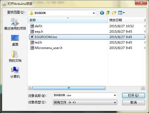
Find the physical location of the program, "voice scenario light/ EGGROOM/ EGGROOM.ino", double-click to open. | Find the physical location of the program, "voice scenario light/ EGGROOM/ EGGROOM.ino", double-click to open. | ||
| Line 188: | Line 189: | ||
Microduino-Core+ | Microduino-Core+ | ||
Microduin-USBTTL | Microduin-USBTTL | ||
| − | + | Note: | |
| − | Microduino-DUO-Vas the base plate, should be reduced the overall height, and at the same time fixes the module Lamp to provide lighting function at the side, and out Microduino-Lamp and Microduino-sensorhub on the top of both sides. When assembling, | + | Microduino-DUO-Vas the base plate, should be reduced the overall height, and at the same time fixes the module Lamp to provide lighting function at the side, and out Microduino-Lamp and Microduino-sensorhub on the top of both sides. When assembling, don't put on Sensorhub at first, so it'll be easy to install below. |
According to way which is shown in the following picture, set the temperature and humidity sensors and microphone and ColorLED on the front panel, and fix them with screws. [[File:Pp2.png||600px|center]] | According to way which is shown in the following picture, set the temperature and humidity sensors and microphone and ColorLED on the front panel, and fix them with screws. [[File:Pp2.png||600px|center]] | ||
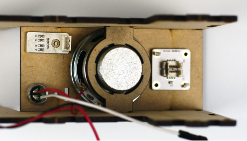
| − | According to the way as shown, use the base to fix the horn on the side panel, and leave the horn line to the left of the picture, which will be convenient for the later installation. | + | According to the way as shown, use the base to fix the horn on the side panel, and leave the horn line to the left of the picture, which will be convenient for the later installation. Don't splice the two side panels and the front panel together, remove the side panel on one side at first, and it'll be easy to continue the subsequent installation. |
[[File:Pp3.png||600px|center]] | [[File:Pp3.png||600px|center]] | ||
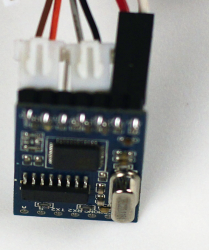
Use wire to connect the voice module, and pay attention to the direction of attachment. The first double interface on the left is GND and VCC. The second double interface is RX and DX. If you are unable to determine the direction, connect the speech recognition module according to the direction in the picture. | Use wire to connect the voice module, and pay attention to the direction of attachment. The first double interface on the left is GND and VCC. The second double interface is RX and DX. If you are unable to determine the direction, connect the speech recognition module according to the direction in the picture. | ||
[[File:Pp4.png||350px|center]] | [[File:Pp4.png||350px|center]] | ||
| − | + | Note: If you want to directly use USBTTL+Sensorhub to test the speech recognition module, the RX and TX of the speech module should be connect in turn to the above picture. | |
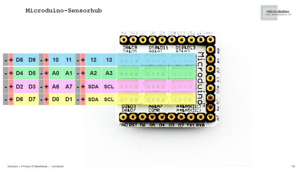
Corresponding to the following picture, use the sensor wire to connect the sensor, ColorLED connects to the A2 port, the temperature and humidity sensor connect to the SDASCL port on the bottom right, and the voice module connects to the D2/D3 port. After connection, insert the Sensorhub into Audio module, and put it at the top. | Corresponding to the following picture, use the sensor wire to connect the sensor, ColorLED connects to the A2 port, the temperature and humidity sensor connect to the SDASCL port on the bottom right, and the voice module connects to the D2/D3 port. After connection, insert the Sensorhub into Audio module, and put it at the top. | ||
[[File:Microduino-sensorhub rule.JPG||600px|center]] | [[File:Microduino-sensorhub rule.JPG||600px|center]] | ||
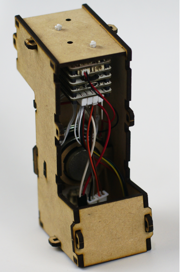
| − | Now the state should be all sensors has connected to Sensorhub, and all modules have stitched on the floor, and the horn is fixed on the side panel with clamp. Then insert the remaining | + | Now the state should be all sensors has connected to Sensorhub, and all modules have stitched on the floor, and the horn is fixed on the side panel with clamp. Then insert the remaining floors into the side panel, and buckle on the other side board. |
[[File:Pp6.png||600px|center]] | [[File:Pp6.png||600px|center]] | ||
Then plug the front and rear panels for fixing the two side plates. Finally, insert the two heads up and down. | Then plug the front and rear panels for fixing the two side plates. Finally, insert the two heads up and down. | ||
| Line 205: | Line 206: | ||
==Overall Debugging== | ==Overall Debugging== | ||
| − | Open the power supply of the voice scene lamp, at first wait the lights lighting up for about 2-3 seconds, then goes out. At this time, say | + | Open the power supply of the voice scene lamp, at first wait the lights lighting up for about 2-3 seconds, then goes out. At this time, say "Paopao" to the microphone, which is the switch sentence for the voice input. That is to say you should say this sentence at first, then are other voice command, after seeing the voice input indicator light lights. Every time after you say one command, there are 5 seconds to say the next one. If there is no voice input the light will be put out, and you need to say "Paopao" again to enter the voice output state. |
| − | In this case the voice switch instruction is | + | In this case the voice switch instruction is "Paopao", so please use mandarin clear voice to say"Paopao", and observe if ColorLED lights. If it lights, you should continue to speak command, such as "tell a story", and the lighting module will be light. If there is no voice replies “hi, I'm Paopao", you should continue to say "Paopao" until the ColorLED lights and there is voice reply, then you can speak another command. |
==Conversation== | ==Conversation== | ||
| − | The trigger voice: | + | The trigger voice: Papao. |
| − | + | ||
| + | Reply: Hi, I'm Paopao. | ||
| + | |||
Your name? | Your name? | ||
| − | + | ||
| + | Reply: My name is Paopao. | ||
| + | |||
Your age? | Your age? | ||
| − | + | ||
| + | Reply: I'm 7 years old. | ||
Tell a story. | Tell a story. | ||
| − | + | ||
| + | Reply: Long long ago, there was a mountain. | ||
| + | |||
Recite a poem. | Recite a poem. | ||
| − | + | ||
| − | + | Reply: OK, I'll recite a poem. | |
| + | |||
| + | Reply: Quiet Night Thought. | ||
| + | |||
Fool. | Fool. | ||
| − | |||
| + | Reply: You just foolish. | ||
| + | |||
| + | |||
| + | What's the weather like? | ||
| − | |||
(According to the temperature) | (According to the temperature) | ||
| − | |||
| − | |||
| − | |||
| + | Reply: ① Pleasant temperature, go out and play. | ||
| + | |||
| + | Reply: ② Today the day is cold, wear more clothes. | ||
| + | |||
| + | Reply: ③ Today's very hot. | ||
| + | |||
| + | It's too black. | ||
| + | |||
| + | Reply: Now?(Turn on the light.) | ||
| − | |||
| − | |||
Turn off the light. | Turn off the light. | ||
| − | + | ||
| + | Reply: OK.(Turn off the light) | ||
| + | |||
Thanks. | Thanks. | ||
| − | + | ||
| + | Reply: You're welcome. | ||
| + | |||
==Attention Problems== | ==Attention Problems== | ||
| − | *Each time the voice inputs command, you should firstly say the content that the f1 corresponds to. In this case the readers of the | + | *Each time the voice inputs command, you should firstly say the content that the f1 corresponds to. In this case the readers of the "Microduino" can input according to their own settings. |
*The judgment of the diode polarity. Reversed grafted, the diode polarity will not emit lighting. | *The judgment of the diode polarity. Reversed grafted, the diode polarity will not emit lighting. | ||
==Program Description== | ==Program Description== | ||
| Line 271: | Line 292: | ||
VOICE.println("{a0sha gua|s0sm}"); //Fool. | VOICE.println("{a0sha gua|s0sm}"); //Fool. | ||
delay(200); | delay(200); | ||
| − | VOICE.println("{a0tian qi ru he|s0wd}"); // | + | VOICE.println("{a0tian qi ru he|s0wd}"); //What's the weather like? |
delay(200); | delay(200); | ||
| − | VOICE.println("{a0hao hei|s0kd}"); // | + | VOICE.println("{a0hao hei|s0kd}"); //It's too dark. |
delay(200); | delay(200); | ||
VOICE.println("{a0guan deng|s0gd}"); //Turn off the light. | VOICE.println("{a0guan deng|s0gd}"); //Turn off the light. | ||
| Line 292: | Line 313: | ||
{ | { | ||
String cmd = ""; | String cmd = ""; | ||
| − | if (VOICE.available()) //If receive the | + | if (VOICE.available()) //If receive the user's speech input data in the speech chip. |
{ | { | ||
cmd += char(VOICE.read()); //Read the content in the serial port. | cmd += char(VOICE.read()); //Read the content in the serial port. | ||
| Line 303: | Line 324: | ||
*Function Realization(Take the temperature as example) | *Function Realization(Take the temperature as example) | ||
<source lang="cpp"> | <source lang="cpp"> | ||
| − | case 5: // | + | case 5: //What's the weather like? |
timer_voice = 0; //Reset the timer . | timer_voice = 0; //Reset the timer . | ||
am2321.read(); //Read the sensor. | am2321.read(); //Read the sensor. | ||
Latest revision as of 08:14, 13 September 2016
ContentsOutline
In this tutorial, we will use Microduino product module to quickly set up alighting control system which can identify the human's voice. The player can quickly start, and can control the on and off of the light module and choose color through speaking. Bill of Material
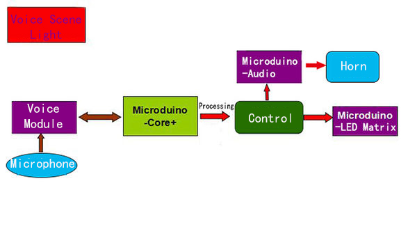
Principle of the ExperimentThe principle of the voice scene lamp module is to record the mapping relation between voice and scenarios, recognize the input voice through the phonics, and return to the core of the corresponding scene number. The core, according to the number obtained, realizes different dialogue under different scenes, including real-time monitoring the indoor temperature, switching light on and off, and so on, through simulating the mouth to control the on and off of the light module. At the same time, there are also some interesting situational dialogues.
The suite use Microduino-Lamp module as light-emitting device, which connect 6 RGB3 colored lights, and can use the corresponding library functions to control the color of every lights. In order to clearly illustrate lights control method, we take a simple program as example. Open Arduino IDE, under the root(File)—>(Examples)—>_99_LCD_NeoPixel, click and open the routine strand test. #include <Adafruit_NeoPixel.h>
#define PIN 6 //Define control pin
// Parameter 1 = The number of the lamps in strip.
// Parameter 2 = The number of the pin
// Parameter 3 = The type of the lamps, and there are multiple choices.(Between the first two choose one, and between the last two choose one.):
// NEO_RGB Pixels are wired for RGB bitstream
// NEO_GRB Pixels are wired for GRB bitstream
// NEO_KHZ400 400 KHz bitstream (e.g. FLORA pixels)
// NEO_KHZ800 800 KHz bitstream (e.g. High Density LED strip)
Adafruit_NeoPixel strip = Adafruit_NeoPixel(60, PIN, NEO_GRB + NEO_KHZ800);
void setup()
{
strip.begin();
strip.show(); //Initialize all the lights out.
}
void loop()
{
// The method to light up the lights.
colorWipe(strip.Color(255, 0, 0), 50); // Light the red.
colorWipe(strip.Color(0, 255, 0), 50); // Light the green.
colorWipe(strip.Color(0, 0, 255), 50); // Light the blue.
rainbow(20);
rainbowCycle(20);
}
//Use the color the "c" represents lit the lamp lights in turn, and every time light a lamp wait "wait" seconds.
void colorWipe(uint32_t c, uint8_t wait)
{
for(uint16_t i = 0; i < strip.numPixels(); i++) //Light in turn.
{
strip.setPixelColor(i, c); //This function is used to light the number i lamp with the color"c" represents.
strip.show(); //This function will display the control information which the setPixelColor function writes.
//Come out, on which is lighted lamp module.
delay(wait);
}
}
void rainbow(uint8_t wait) // Rainbow shows.
{
uint16_t i, j;
for(j = 0; j < 256; j++) //Gradient 255 colors.
{
for(i = 0; i < strip.numPixels(); i++) //Light lamps in turn, and wait about wait seconds apart.
{
strip.setPixelColor(i, Wheel((i + j) & 255));
}
strip.show();
delay(wait);
}
}
// Add the cycle of the rainbow, which is a slight different from the above function.
void rainbowCycle(uint8_t wait)
{
uint16_t i, j;
for(j = 0; j < 256 * 5; j++) //The rainbow cycles 5 times.
{
for(i = 0; i < strip.numPixels(); i++)
{
strip.setPixelColor(i, Wheel(((i * 256 / strip.numPixels()) + j) & 255)); //The mathematical transformation added for the cycle.
}
strip.show();
delay(wait);
}
}
// Input any number between 0-255 to get the only corresponding color.
// The color will gradient cycle from red->green->blue->red in turn.
uint32_t Wheel(byte WheelPos)
{
if(WheelPos < 85)
{
return strip.Color(WheelPos * 3, 255 - WheelPos * 3, 0);
}
else if(WheelPos < 170)
{
//Because WheelPos * 3 will surpass 255 in the case of 85 to 170, so it should first subtract 85 itself.
WheelPos -= 85;
return strip.Color(255 - WheelPos * 3, 0, WheelPos * 3);
}
else
{
//Because WheelPos * 3 will surpass 255 in the case of over 170, so it should subtract 170 first itself.
WheelPos -= 170;
return strip.Color(0, WheelPos * 3, 255 - WheelPos * 3);
}DocumentThe code of the voice scenario light: [Code to download] The voice scene light sound file: [Audio to download]
Debug Process
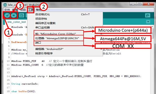
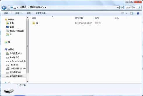
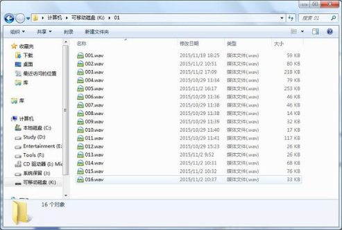
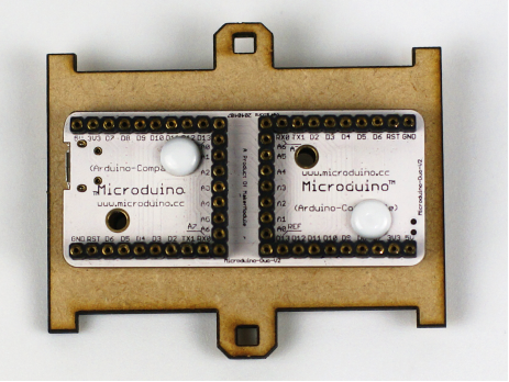
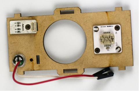
Overlay Microduino-Core+ and Microduino-USBTTL together. Use cable to upload the written program to Microduino-Core+ through Microduino-USBTTL. Note: Please upload programs before stacking all modules together. Find the physical location of the program, "voice scenario light/ EGGROOM/ EGGROOM.ino", double-click to open. Program download Click "√", and compile the program. Click [Tool], and choose the right board + processor +port. Click "→", and upload.
Install TF card to the module Audio, then use USB cable to connect the module Audio to the computer. At this time it will identify a removable disk. Create a new folder named as 01 in the disk that have been recognized, then copy the voice to the folder 01 according to the number sequence of the name. At this point the audio are stored. Set UpFix the baseboard Microduino-Duo-Von the roof with screws. The shape of the roof and bottom plate are same. Set up the hardware circuit, and stack up the devices that will be used. Microduino-Amplifier Microduino-Audio Microduino-sensorhub Place the above module at one end of Duo-V. Microduino-Duo-V Place the following modules at the other end of Duo-V. Microduino-Lamp Microduino-Core+ Microduin-USBTTL Note: Microduino-DUO-Vas the base plate, should be reduced the overall height, and at the same time fixes the module Lamp to provide lighting function at the side, and out Microduino-Lamp and Microduino-sensorhub on the top of both sides. When assembling, don't put on Sensorhub at first, so it'll be easy to install below. According to way which is shown in the following picture, set the temperature and humidity sensors and microphone and ColorLED on the front panel, and fix them with screws.According to the way as shown, use the base to fix the horn on the side panel, and leave the horn line to the left of the picture, which will be convenient for the later installation. Don't splice the two side panels and the front panel together, remove the side panel on one side at first, and it'll be easy to continue the subsequent installation. Use wire to connect the voice module, and pay attention to the direction of attachment. The first double interface on the left is GND and VCC. The second double interface is RX and DX. If you are unable to determine the direction, connect the speech recognition module according to the direction in the picture. Note: If you want to directly use USBTTL+Sensorhub to test the speech recognition module, the RX and TX of the speech module should be connect in turn to the above picture. Corresponding to the following picture, use the sensor wire to connect the sensor, ColorLED connects to the A2 port, the temperature and humidity sensor connect to the SDASCL port on the bottom right, and the voice module connects to the D2/D3 port. After connection, insert the Sensorhub into Audio module, and put it at the top. Now the state should be all sensors has connected to Sensorhub, and all modules have stitched on the floor, and the horn is fixed on the side panel with clamp. Then insert the remaining floors into the side panel, and buckle on the other side board. Then plug the front and rear panels for fixing the two side plates. Finally, insert the two heads up and down. Finally use bolt to fix all fixed buckle. Overall DebuggingOpen the power supply of the voice scene lamp, at first wait the lights lighting up for about 2-3 seconds, then goes out. At this time, say "Paopao" to the microphone, which is the switch sentence for the voice input. That is to say you should say this sentence at first, then are other voice command, after seeing the voice input indicator light lights. Every time after you say one command, there are 5 seconds to say the next one. If there is no voice input the light will be put out, and you need to say "Paopao" again to enter the voice output state. In this case the voice switch instruction is "Paopao", so please use mandarin clear voice to say"Paopao", and observe if ColorLED lights. If it lights, you should continue to speak command, such as "tell a story", and the lighting module will be light. If there is no voice replies “hi, I'm Paopao", you should continue to say "Paopao" until the ColorLED lights and there is voice reply, then you can speak another command. ConversationThe trigger voice: Papao. Reply: Hi, I'm Paopao.
Reply: My name is Paopao.
Reply: I'm 7 years old.
Reply: Long long ago, there was a mountain.
Reply: OK, I'll recite a poem. Reply: Quiet Night Thought.
Reply: You just foolish.
(According to the temperature) Reply: ① Pleasant temperature, go out and play. Reply: ② Today the day is cold, wear more clothes. Reply: ③ Today's very hot. It's too black. Reply: Now?(Turn on the light.)
Reply: OK.(Turn off the light)
Reply: You're welcome.
Attention Problems
Program Description
void writecommand()
{
    VOICE.println("{d1}");
    delay(200);
    VOICE.println("{d1}");    //Confirm to enter a debug mode.
    delay(200);
    VOICE.println("{c0}");      //Clear the existing instruction.
    delay(200);
    VOICE.println("{a0pao pao|s0pp}");  //Open voice commands.
    delay(200);
    VOICE.println("{a0ni de ming zi|s0mz}"); //Your name.
    delay(200);
    VOICE.println("{a0ni de nian ling|s0nl}");  // Your age.
    delay(200);
    VOICE.println("{a0jiang gu shi|s0gs}");   //Tell a story.
    delay(200);
    VOICE.println("{a0bei shi|s0sg}"); //Recite a poem.
    delay(200);
    VOICE.println("{a0sha gua|s0sm}"); //Fool.
    delay(200);
    VOICE.println("{a0tian qi ru he|s0wd}"); //What's the weather like?
    delay(200);
    VOICE.println("{a0hao hei|s0kd}");  //It's too dark.
    delay(200);
    VOICE.println("{a0guan deng|s0gd}");  //Turn off the light.
    delay(200);
    VOICE.println("{a0zai jian|s0zj}");  //Good-bye.
    delay(200);
    VOICE.println("{a0xie xie|s0xx}");  //Thanks.
    delay(200);
    VOICE.println("{l0}");     //Load.
    delay(200);
    VOICE.println("{d0}");    //Exit the debugging.
    delay(200);
}
if (VOICE.available())
{
    String cmd = "";
    if (VOICE.available()) //If receive the user's speech input data in the speech chip.
    {
        cmd += char(VOICE.read()); //Read the content in the serial port.
        delay(10);
        cmd += char(VOICE.read());
        delay(10);
    }
}
case 5:                       //What's the weather like?
timer_voice = 0;        //Reset the timer .
am2321.read();           //Read the sensor.
temperature = am2321.temperature / 10.0;
Serial.println(temperature);    //Debuguse.
if(temperature < 20)AUDIO.choose(15);   //According to the temperature play different voice.
if(temperature >= 20 && temperature < 27)AUDIO.choose(14);
if(temperature >= 27)AUDIO.choose(16);
timer_voice = millis();            //Lock-in time
break;
video |
