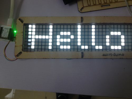
Difference between revisions of "Open Source LED Dot Matrix Clock"
| (11 intermediate revisions by 3 users not shown) | |||
| Line 5: | Line 5: | ||
| | | | ||
==Outline== | ==Outline== | ||
| − | * | + | *Project: Microduino dot matrix cascade clock |
| − | * | + | *Objective: Real-time display clocks and characters. |
| − | * | + | *Difficulty: Medium |
*Time-consuming:2 hours | *Time-consuming:2 hours | ||
| − | * | + | *Maker: peng |
*Introduction: | *Introduction: | ||
| − | **Cascade the four [[Microduino | + | **Cascade the four [[Microduino DotMatrix]] module. |
**Use a Bluetooth module to calibrate the time that the dot matrix displays through the mobile APP. | **Use a Bluetooth module to calibrate the time that the dot matrix displays through the mobile APP. | ||
**You can also send any character to dot matrix module to display through APP. | **You can also send any character to dot matrix module to display through APP. | ||
| Line 30: | Line 30: | ||
|[[Microduino-RTC]]||1||To read access time | |[[Microduino-RTC]]||1||To read access time | ||
|- | |- | ||
| − | |[[Microduino- | + | |[[Microduino-BLE]]||1||Communication between the mobile phone and Core |
|- | |- | ||
| − | |[[Microduino- | + | |[[Microduino-Dot Matrix]]||4||To display |
|- | |- | ||
| − | |[[Microduino-Cube-S1]]||1|| | + | |[[Microduino-Cube-S1]]||1||Extension |
|} | |} | ||
|width="50%" valign="top" align="left"| | |width="50%" valign="top" align="left"| | ||
| + | |||
===Other Material=== | ===Other Material=== | ||
{|class="wikitable" | {|class="wikitable" | ||
| Line 46: | Line 47: | ||
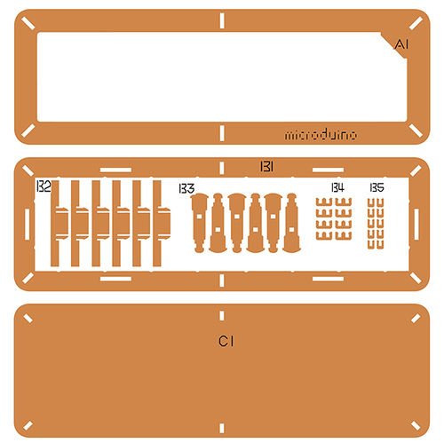
|LED dot matrix clock shell suite || 1 ||Shell | |LED dot matrix clock shell suite || 1 ||Shell | ||
|- | |- | ||
| − | |Double sides adhesive tape || | + | |Double sides adhesive tape || 8 ||Stick shell |
| + | |- | ||
| + | |Nylon screws || 4 ||To fix the shell | ||
| + | |} | ||
|} | |} | ||
| + | {| border="0" cellpadding="10" width="100%" | ||
| + | |- | ||
| + | |width="50%" valign="top" align="left"| | ||
| + | [[File:matrixBOM1.jpg||500px|center]] | ||
| + | |||
| + | |width="50%" valign="top" align="left"| | ||
| + | [[File:matrixBOM2.jpg||500px|center]] | ||
| + | |||
|} | |} | ||
==Principle of the Experiment== | ==Principle of the Experiment== | ||
| − | *Features of the '''[[Microduino- Dot Matrix]]''' | + | *Features of the '''[[Microduino-Dot Matrix]]''' module: |
| − | **The module is 8x8 dot matrix, and the size is 60mm* | + | **The module is 8x8 dot matrix, and the size is 60mm*60mm; |
**The color display quality of each dot is 24 bits, and the color display effect is 32k; | **The color display quality of each dot is 24 bits, and the color display effect is 32k; | ||
**Support the IIC communication protocol. The IIC address can be set(1~64). The dot matrix sequence adopts the plane rectangular coordinate system, which is easy to control; | **Support the IIC communication protocol. The IIC address can be set(1~64). The dot matrix sequence adopts the plane rectangular coordinate system, which is easy to control; | ||
| − | *Use '''[[Microduino- BLE]]''' Bluetooth module to communicate with the mobile phone: | + | *Use '''[[Microduino-BLE]]''' Bluetooth module to communicate with the mobile phone: |
**The mobile APP sends the string to '''core module''' through the '''Bluetooth module''', and display on the '''dot matrix module'''. | **The mobile APP sends the string to '''core module''' through the '''Bluetooth module''', and display on the '''dot matrix module'''. | ||
==Program Download== | ==Program Download== | ||
*Please keep to download and download the Microduino official latest IDE. | *Please keep to download and download the Microduino official latest IDE. | ||
| − | *Download a program from the link below:'''[https://github.com/ | + | *Download a program from the link below:'''[https://github.com/Microduino/Dot_Maxtrix_Clock Dot-Matrix-Clock.ino]''' |
==Programming== | ==Programming== | ||
*Overlay the '''[[Microduino-Core]]''' and '''[[Microduino-USBTTL]]''' together. | *Overlay the '''[[Microduino-Core]]''' and '''[[Microduino-USBTTL]]''' together. | ||
**Connect the '''[[Microduino-USBTTL]]''' with USE cable and prepare to upload the programs. | **Connect the '''[[Microduino-USBTTL]]''' with USE cable and prepare to upload the programs. | ||
| − | ** | + | **Note: Please upload programs before stacking all modules together. |
*Open Arduino IDE for Microduino environment. (The reference to set up:'''[[AVR Core:Getting started]]''') | *Open Arduino IDE for Microduino environment. (The reference to set up:'''[[AVR Core:Getting started]]''') | ||
*Click '''[Tool]''', and confirm '''board card(Microduino-Core), and processor(Atmega328P@16M,5V)''' selected correctly, and select the corresponding '''port number (COMX)'''. | *Click '''[Tool]''', and confirm '''board card(Microduino-Core), and processor(Atmega328P@16M,5V)''' selected correctly, and select the corresponding '''port number (COMX)'''. | ||
| − | *Click '''[File]'''->'''[Open]''', browse to the project program address, and click''' | + | *Click '''[File]'''->'''[Open]''', browse to the project program address, and click'''"Dot-Matrix-Clock.ino"''' to open the program. |
*After all these items are correct, click '''"→"''' to download the program to the development board. | *After all these items are correct, click '''"→"''' to download the program to the development board. | ||
| Line 78: | Line 90: | ||
|width="50%" valign="top" align="left"| | |width="50%" valign="top" align="left"| | ||
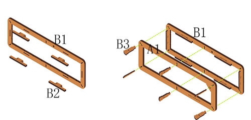
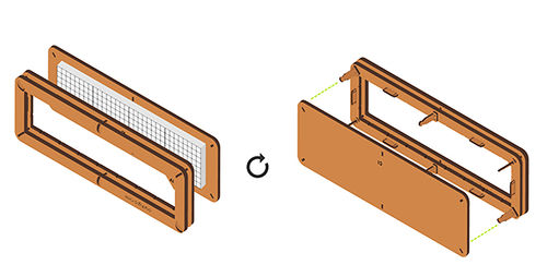
*'''Step1''': | *'''Step1''': | ||
| − | **Insert | + | **Insert '''structure B2''' vertically into '''structure B1'''. |
| + | **Use '''structure B3''' to connect '''structure A1''' and '''structure B1'''. | ||
|width="50%" valign="top" align="left"| | |width="50%" valign="top" align="left"| | ||
[[File:DotMatrixjiegou1.jpg|500px|center|thumb]] | [[File:DotMatrixjiegou1.jpg|500px|center|thumb]] | ||
|} | |} | ||
| − | |||
{| border="0" cellpadding="10" width="100%" | {| border="0" cellpadding="10" width="100%" | ||
| Line 88: | Line 100: | ||
|width="50%" valign="top" align="left"| | |width="50%" valign="top" align="left"| | ||
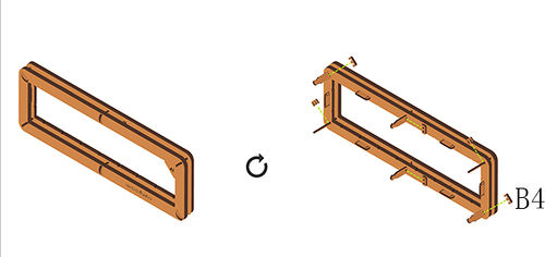
*'''Step2''': | *'''Step2''': | ||
| − | **Use '''structure | + | **Use '''structure B4'''to jam the '''structure A1''' and '''structure B1''' . |
|width="50%" valign="top" align="left"| | |width="50%" valign="top" align="left"| | ||
| − | [[File: | + | [[File:DotMatrixjiegou3.jpg|500px|center|thumb]] |
|} | |} | ||
| Line 98: | Line 110: | ||
|width="50%" valign="top" align="left"| | |width="50%" valign="top" align="left"| | ||
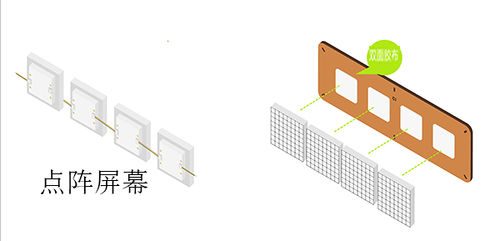
*'''Step3''': | *'''Step3''': | ||
| − | ** | + | **To change the IIC address of the dot matrix module, you can refer to '''[[https://www.microduino.cn/wiki/index.php/Microduino-Module_Dot_Matrix#.E7.82.B9.E9.98.B5.E5.9C.B0.E5.9D.80.E8.AE.BE.E7.BD.AE.E6.96.B9.E6.B3.95 The method of setting the IIC address of the dot matrix module ]]''' tutorial. |
| + | **Connect the dot matrix modules of which the IIC address have been changed in order that from left to right according to to defined address, to complete the cascade. | ||
| + | **Stick piece of four double sides adhesive tape on the back of '''structure C1''' equidistantly, and stick '''[[Microduino-Dot Matrix]]''' to '''structure C1'''('''put the side with letters of the dot matrix down''')successively. | ||
| + | **As the following figure, reserve the cable of the '''key end interface''' of the module in order to connect the '''IIC interface''' of '''[[Microduino-Cube-S1]]'''. | ||
|width="50%" valign="top" align="left"| | |width="50%" valign="top" align="left"| | ||
| − | [[File: | + | [[File:DotMatrix1jilian.jpg|500px|center|thumb]] |
|} | |} | ||
| Line 108: | Line 123: | ||
|width="50%" valign="top" align="left"| | |width="50%" valign="top" align="left"| | ||
*'''Step4''': | *'''Step4''': | ||
| − | ** | + | **Use '''structure B3''' to connect '''structure C1''' and '''structure A1,B1'''. |
| − | |||
| − | |||
|width="50%" valign="top" align="left"| | |width="50%" valign="top" align="left"| | ||
| − | [[File: | + | [[File:DotMatrixjiegou4.jpg|500px|center|thumb]] |
|} | |} | ||
| Line 120: | Line 133: | ||
|width="50%" valign="top" align="left"| | |width="50%" valign="top" align="left"| | ||
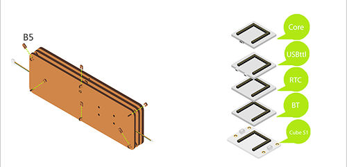
*'''Step5''': | *'''Step5''': | ||
| − | **Use | + | **Use '''structure B5''' to jam '''structure B3'''. |
| + | **Stack the following modules on the '''[[Microduino-Cube-S1]]'''. | ||
| + | ***'''[[Microduino-Core]]''' | ||
| + | ***'''[[Microduino-USBTTL]]''' | ||
| + | ***'''[[Microduino-RTC]]''' | ||
| + | ***'''[[Microduino-BT]]''' | ||
|width="50%" valign="top" align="left"| | |width="50%" valign="top" align="left"| | ||
| − | [[File: | + | [[File:DotMatrixjiegou7.jpg|500px|center|thumb]] |
|} | |} | ||
| − | |||
{| border="0" cellpadding="10" width="100%" | {| border="0" cellpadding="10" width="100%" | ||
| Line 130: | Line 147: | ||
|width="50%" valign="top" align="left"| | |width="50%" valign="top" align="left"| | ||
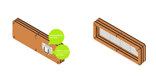
*'''Step6''': | *'''Step6''': | ||
| − | + | **Connect the module '''[[Microduino-Dot Matrix]]''' to the '''IIC interface''' of '''[[Microduino-Cube-S1]]'''. | |
| − | + | **Use '''nylon screws''' to fix '''[[Microduino-Cube-S1]]''' on the back of '''structure C1'''. | |
| − | |||
| − | |||
| − | |||
| − | **Connect the '''[[Microduino- Dot Matrix]]''' | ||
| − | **Use | ||
|width="50%" valign="top" align="left"| | |width="50%" valign="top" align="left"| | ||
| Line 148: | Line 160: | ||
|- | |- | ||
|width="50%" valign="top" align="left"| | |width="50%" valign="top" align="left"| | ||
| − | *Make sure that the phone Bluetooth has been open, then use APP to search the Bluetooth device named as ''' | + | *Make sure that the phone Bluetooth has been open, then use APP to search the Bluetooth device named as '''"Microduino"'''. |
*After connecting successfully, you can control it. | *After connecting successfully, you can control it. | ||
===Calibration Time=== | ===Calibration Time=== | ||
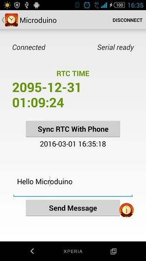
*In view of RTC module will lost time long time without power supply, we have added that use APP to adjust time, through the Bluetooth module. | *In view of RTC module will lost time long time without power supply, we have added that use APP to adjust time, through the Bluetooth module. | ||
| − | **Clicking the ''' | + | **Clicking the '''"sync time with phone"''' button can adjust the time of the dot matrix. |
|width="50%" valign="top" align="left"| | |width="50%" valign="top" align="left"| | ||
[[File:DcolorMatrix ble.jpg|300px|center|thumb]] | [[File:DcolorMatrix ble.jpg|300px|center|thumb]] | ||
| Line 163: | Line 175: | ||
|- | |- | ||
|width="50%" valign="top" align="left"| | |width="50%" valign="top" align="left"| | ||
| − | *In the input field | + | *In the input field write'hello microduino', and click '''"send message"''', then the characters that you have written will be displayed on the dot matrix screen. |
|width="50%" valign="top" align="left"| | |width="50%" valign="top" align="left"| | ||
[[File:DotMatrixBle.jpg|500px|center|thumb]] | [[File:DotMatrixBle.jpg|500px|center|thumb]] | ||
| Line 169: | Line 181: | ||
==Code Instruction== | ==Code Instruction== | ||
| − | Code to | + | Code to loading: [[File:Dot Maxtrix Clock.zip]] |
===Dot Matrix Cascade=== | ===Dot Matrix Cascade=== | ||
uint8_t Addr[MatrixPix_X][MatrixPix_Y] = { | uint8_t Addr[MatrixPix_X][MatrixPix_Y] = { | ||
| Line 191: | Line 203: | ||
From the address where the "t" character first appears in buffer, read the value according to the %d type, and write into sta[]. | From the address where the "t" character first appears in buffer, read the value according to the %d type, and write into sta[]. | ||
bleUpdata() | bleUpdata() | ||
| − | Transfer data through UART, only by clicking the button on your mobile phone to send the specified character. If loosing, it will send | + | Transfer data through UART, only by clicking the button on your mobile phone to send the specified character. If loosing, it will send character"0". So without press, it will always show time. |
===RTC=== | ===RTC=== | ||
| Line 206: | Line 218: | ||
display.print(second() % 2 ? " " : ":"); | display.print(second() % 2 ? " " : ":"); | ||
| − | The second flashes, after being used justify whether the second can be exactly divided by 2. If it can, show it. If not, | + | The second flashes, after being used justify whether the second can be exactly divided by 2. If it can, show it. If not, don't show. |
display.getDeviceAddr(a) | display.getDeviceAddr(a) | ||
Get the IIC address of the device. | Get the IIC address of the device. | ||
| Line 216: | Line 228: | ||
Clean up the screen. | Clean up the screen. | ||
display.setColor(X,Y,Z) | display.setColor(X,Y,Z) | ||
| − | Set the color of the full screen | + | Set the color of the full screen X:Red Y:Green Z:Blue |
display.writeString("string", MODE, time ,z) | display.writeString("string", MODE, time ,z) | ||
| − | + | string: any string. | |
| − | + | MODE: MODE_H displays characters horizontally. /MODE_V displays characters vertically. | |
| − | + | time: The displayed time(the flow velocity of the characters on the screen). | |
| − | + | z: X/Y coordinate. | |
Through reading the RTC color, display the specific values in the form of coordinates. | Through reading the RTC color, display the specific values in the form of coordinates. | ||
== FAQ== | == FAQ== | ||
| − | *Q:'''How can I know the IIC address of the '''[[Microduino- | + | *Q:'''How can I know the IIC address of the '''[[Microduino-Dot Matrix]]''' module?''' |
**A:Refer to '''[[https://www.microduino.cn/wiki/index.php/Microduino-Module_Dot_Matrix/zh#.E7.82.B9.E9.98.B5.E5.9C.B0.E5.9D.80.E8.AE.BE.E7.BD.AE.E6.96.B9.E6.B3.95 The method of setting the IIC address of the dot matrix module]]''' tutorial. | **A:Refer to '''[[https://www.microduino.cn/wiki/index.php/Microduino-Module_Dot_Matrix/zh#.E7.82.B9.E9.98.B5.E5.9C.B0.E5.9D.80.E8.AE.BE.E7.BD.AE.E6.96.B9.E6.B3.95 The method of setting the IIC address of the dot matrix module]]''' tutorial. | ||
*Q:'''What order do the lattice modules connect according to?''' | *Q:'''What order do the lattice modules connect according to?''' | ||
| Line 233: | Line 245: | ||
**A:When there is connected displayed on the top left in the APP interface, it is connected successfully. | **A:When there is connected displayed on the top left in the APP interface, it is connected successfully. | ||
*Q:'''What is the meaning of the jumper of the Bluetooth module?''' | *Q:'''What is the meaning of the jumper of the Bluetooth module?''' | ||
| − | **A:The Bluetooth module used in this tutorial is the default soft serial port mySerial(4,5), so | + | **A:The Bluetooth module used in this tutorial is the default soft serial port mySerial(4,5), so don't need to jump line. You can refer to the blue module configuration for in-depth knowledge of the Bluetooth. [https://www.microduino.cn/wiki/index.php/Microduino-Module_BLE/zh#.E5.BC.95.E8.84.9A.E8.AF.B4.E6.98.8E Microduino- BLE pin elucidation]. |
|} | |} | ||
Latest revision as of 08:01, 13 September 2016
| Language: | English • 中文 |
|---|
ContentsOutline
Bill of Materials
Principle of the Experiment
Program Download
Programming
**Note: Please upload programs before stacking all modules together.
Installation
Operating Instruction
Bluetooth Connection
Display Text
Code InstructionCode to loading: File:Dot Maxtrix Clock.zip Dot Matrix Cascade uint8_t Addr[MatrixPix_X][MatrixPix_Y] = {
{ 64, 63, 62, 61}};
Define the IIC addresses of the four Dot Matrix modules as 64, 63, 62, and 61, and the arrangement type is 1x4. Bluetooth while (mySerial.available()) {...}
It is effective when there is a serial port data. mySerial.read() Red the data which is transferred by the UART. if (c == 't' && buffer_num == 0 && !buffer_sta_d)
buffer_sta_t = true;
if (c == 'm' && buffer_num == 0 && !buffer_sta_t)
buffer_sta_d = true;
Judge it is date or time data. strstr((char *)buffer, "t") Return the address where the "t" character first appears in buffer. sscanf((char *)strstr((char *)buffer, "t"), "t%d,%d,%d,%d,%d,%d", &sta[0], &sta[1], &sta[2], &sta[3], &sta[4], &sta[5]); From the address where the "t" character first appears in buffer, read the value according to the %d type, and write into sta[]. bleUpdata() Transfer data through UART, only by clicking the button on your mobile phone to send the specified character. If loosing, it will send character"0". So without press, it will always show time. RTCrtc.getDate(); rtc.getTime(); setTime(rtc.getHour(), rtc.getMinute(), rtc.getSecond(), rtc.getDay(), rtc.getMonth(), rtc.getYear()) Get the date and time data of rtc. rtc.setDate(day(), weekday() , month(), 0, year() - 2000); //day, weekday, month, century(1=1900, 0=2000), year(0-99) rtc.setTime(hour(), minute() , second()); //hr, min, sec Set by hour, minute, second, day, month, and year format. Displaydisplay.print(second() % 2 ? " " : ":"); The second flashes, after being used justify whether the second can be exactly divided by 2. If it can, show it. If not, don't show. display.getDeviceAddr(a) Get the IIC address of the device. display.getWidth(),display.getHeight() Return the X,Y coordinates. display.setLedColor(x, y, random(0, 255), random(0, 255), random(0, 255)) Set the color of each LED randomly. display.clearDisplay() Clean up the screen. display.setColor(X,Y,Z) Set the color of the full screen X:Red Y:Green Z:Blue display.writeString("string", MODE, time ,z)
string: any string. MODE: MODE_H displays characters horizontally. /MODE_V displays characters vertically. time: The displayed time(the flow velocity of the characters on the screen). z: X/Y coordinate. Through reading the RTC color, display the specific values in the form of coordinates. FAQ
|

