Difference between revisions of "Lesson 38--Microduino Stepper Motor Drive"
From Microduino Wiki
(Created page with "{{Language|第三十八课--Microduino 步进电机驱动}} {| style="width: 800px;" |- | ==Objective== This lesson will show you how to control the stepper motor by Microduin...") |
|||
| Line 4: | Line 4: | ||
| | | | ||
==Objective== | ==Objective== | ||
| − | This lesson will show you how to control the | + | This lesson will show you how to control the stepping motor by Microduino-Stepper module, and welding the step motor control board. |
==Equipment== | ==Equipment== | ||
*'''[[Microduino-Core]]''' | *'''[[Microduino-Core]]''' | ||
| − | *'''[[Microduino- | + | *'''[[Microduino-USBTTL]]''' |
| − | *'''[[Microduino- | + | *'''[[Microduino-Stepper]]''' |
*Other equipments: | *Other equipments: | ||
**USB cable | **USB cable | ||
| Line 20: | Line 20: | ||
==Stepper motor== | ==Stepper motor== | ||
| − | *Connection method for | + | *Connection method for the stepping motor: |
| − | Connect the stepper motor to Microduino | + | Connect the stepper motor to Microduino-Stepper module: |
**Four wire two phase stepper motor has two sets of coil A and B, each group coil's resistance is very small, only a few ohm. A and B group is absolutely insulation and disconnected. Measured with a multimeter, connected is a set; | **Four wire two phase stepper motor has two sets of coil A and B, each group coil's resistance is very small, only a few ohm. A and B group is absolutely insulation and disconnected. Measured with a multimeter, connected is a set; | ||
**After measured group A and B, connect one group coil to OUT1A and OUT1B, the other group coil connects to OUT2A and OUT2B; | **After measured group A and B, connect one group coil to OUT1A and OUT1B, the other group coil connects to OUT2A and OUT2B; | ||
| − | **By changing the MS1 & MS2 to change the stepping mode (Microduino | + | **By changing the MS1 & MS2 to change the stepping mode (Microduino-Stepper uses 1/16 stepping mode by default). |
*Angle calculation: | *Angle calculation: | ||
| − | Stepper motor parameters:1.8deg/ | + | Stepper motor parameters:1.8deg/step, that is stepper motor moves one step turned every 1.8°. |
**Step number=360/1.8*16=3200 step | **Step number=360/1.8*16=3200 step | ||
| Line 38: | Line 38: | ||
[[File:Stepper_motor.jpg|600px|center|thumb]] | [[File:Stepper_motor.jpg|600px|center|thumb]] | ||
| − | == | + | ==Debugging== |
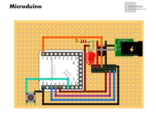
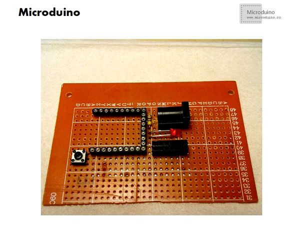
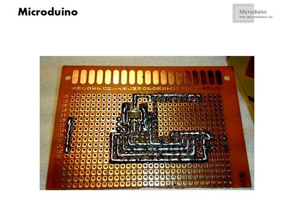
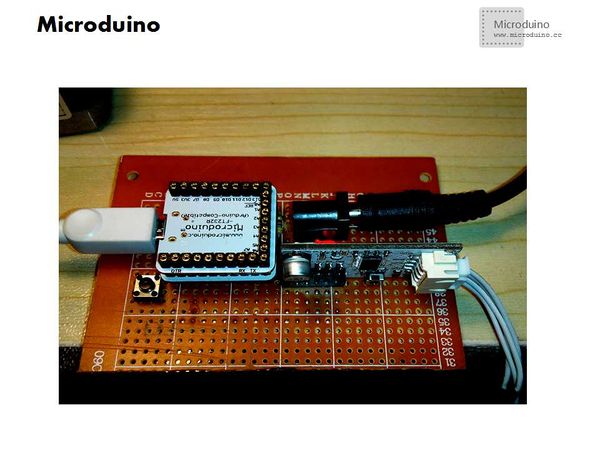
*Step 1:Crop the pegboard as specified size; | *Step 1:Crop the pegboard as specified size; | ||
| Line 58: | Line 58: | ||
==Result== | ==Result== | ||
| − | We can control the four wire two phase | + | We can control the four-wire two-phase stepping motor successfully by Microduino-Stepper module. |
==Video== | ==Video== | ||
http://v.youku.com/v_show/id_XNjg5MTcwOTA0.html | http://v.youku.com/v_show/id_XNjg5MTcwOTA0.html | ||
|} | |} | ||
Latest revision as of 01:31, 12 February 2016
| Language: | English • 中文 |
|---|
ObjectiveThis lesson will show you how to control the stepping motor by Microduino-Stepper module, and welding the step motor control board. Equipment
Stepper motor
Connect the stepper motor to Microduino-Stepper module:
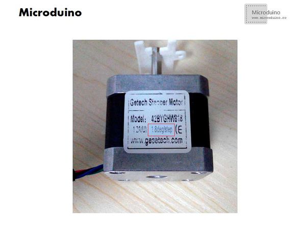
Stepper motor parameters:1.8deg/step, that is stepper motor moves one step turned every 1.8°.
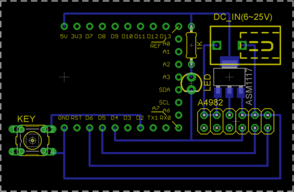
Multiplied by 16 because Microduino A4982 default use 1/16 step mode. SchematicDebugging
Program
ResultWe can control the four-wire two-phase stepping motor successfully by Microduino-Stepper module. Video |
