Difference between revisions of "Microduino-Module USBTTL"
From Microduino Wiki
(→Applications) |
(→FQA) |
||
| (4 intermediate revisions by one other user not shown) | |||
| Line 46: | Line 46: | ||
| | | | ||
| − | == | + | ==FAQ== |
*Can the external power work with Microduino-USBTTL for power supply? | *Can the external power work with Microduino-USBTTL for power supply? | ||
**'''• Since the current of USBTTL is small (less than 100ma), we don't suggest using them together. You can only use USBTTL during the testing phase and are allowed to use the external power supply after finishing the program debugging. | **'''• Since the current of USBTTL is small (less than 100ma), we don't suggest using them together. You can only use USBTTL during the testing phase and are allowed to use the external power supply after finishing the program debugging. | ||
| Line 59: | Line 59: | ||
|- | |- | ||
| | | | ||
| − | |||
| − | |||
| − | |||
| − | |||
| − | |||
| − | |||
| − | |||
| − | |||
| − | |||
| − | |||
==Pictures== | ==Pictures== | ||
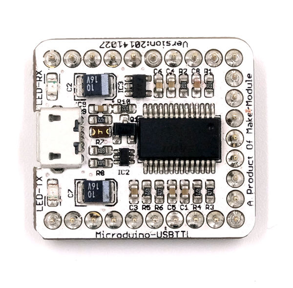
[[file:Micromodule-FT232R-t.jpg|thumb|600px|center|Micromodule FT232R Front]] | [[file:Micromodule-FT232R-t.jpg|thumb|600px|center|Micromodule FT232R Front]] | ||
| Line 74: | Line 64: | ||
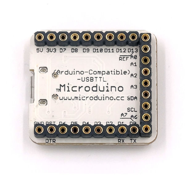
[[file:Micromodule-FT232R-b.jpg|thumb|600px|center|Micromodule FT232R Back]] | [[file:Micromodule-FT232R-b.jpg|thumb|600px|center|Micromodule FT232R Back]] | ||
|} | |} | ||
| + | ==History== | ||
| + | *On July 7, 2013, published the new version of Microduino-USB2TTL, mainly solving the problem of recognition and USB robustness. | ||
| + | *On February 27, 2013, canceled the self-recovery fuse version. Its compatibility was poor, and it was easy to lead the computer couldn’t identity the serial port. | ||
| + | *On January 15, 2013, published the version replacing the D1 with 500mA self-recovery fuse, and players could choose the schottky diode or self-recovery fuse by themselves. | ||
| + | *On November 17, 2012, published the first external version, modified the problems found in the last version. | ||
| + | *on November 5, 2012, the first sample was worked out, The main problems are: | ||
| + | ** The 5V power source hadn’t been connected to the Microduino interface. | ||
| + | ** Micro USB interface block was not strong, and it would be damaged after being sued for a long time. | ||
| + | **D1 was a schottky diode, and it was to prevent the current reflux and for current protection. The rated current was 500mA, and it could be burn down because of the input or output short circuit or too large output current. | ||
| + | |||
| + | '''[[Microduino-FT232R]]''' | ||
Latest revision as of 17:02, 7 February 2017
| Language: | English • 中文 |
|---|
|
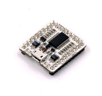
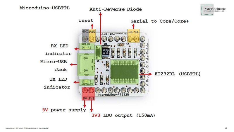
Microduino-USBTTL is based on FDTI FT232RL chip (Arduino embedded driver). It can be stacked with Microduino-Core or Microduino-Core+, enable Microduino core modules to communicate with PC.
|
Contents[hide]FeaturesSpecificationThe USBTTL is an interface conversion chip, which can achieve the conversion from USB to the serial UART interface or to the synchronous/asynchronous Bit-Bang interface mode. FTDI provides driving programs under all kinds of operation systems. Microduino-USBTTL is arduino compatible with simple design, easy to use.
|
Documents
|
DevelopmentDownload the program of the driver:http://www.ftdichip.com/Drivers/VCP.htm |
ApplicationsThe USB2TTL datasheet at DS_FT232R says you can draw up to 50 mA from the FT232R 3.3V output. |
FAQ
|
Buy |
Pictures |
History
- On July 7, 2013, published the new version of Microduino-USB2TTL, mainly solving the problem of recognition and USB robustness.
- On February 27, 2013, canceled the self-recovery fuse version. Its compatibility was poor, and it was easy to lead the computer couldn’t identity the serial port.
- On January 15, 2013, published the version replacing the D1 with 500mA self-recovery fuse, and players could choose the schottky diode or self-recovery fuse by themselves.
- On November 17, 2012, published the first external version, modified the problems found in the last version.
- on November 5, 2012, the first sample was worked out, The main problems are:
- The 5V power source hadn’t been connected to the Microduino interface.
- Micro USB interface block was not strong, and it would be damaged after being sued for a long time.
- D1 was a schottky diode, and it was to prevent the current reflux and for current protection. The rated current was 500mA, and it could be burn down because of the input or output short circuit or too large output current.


