Difference between revisions of "Open Source Self-balance Robot System"
(Created page with "{| style="width: 800px;" |- | ==Outline== *Project: Microduino Self-balance Car *Objective: To make a self-balance car that can be controlled with a remote controller. *Diff...") |
(→Principle of the Experiment) |
||
| Line 96: | Line 96: | ||
PID algorithm adopts proportion, integral and differential to control. Three methods correspond to a constant quantity, that is pconst, iconst and dconst respectively. These three constants are acquired under times of experiment. We can use a mathematical formula to express PID as follows: | PID algorithm adopts proportion, integral and differential to control. Three methods correspond to a constant quantity, that is pconst, iconst and dconst respectively. These three constants are acquired under times of experiment. We can use a mathematical formula to express PID as follows: | ||
e=Expected value - input value. | e=Expected value - input value. | ||
| − | [[File: | + | [[File:1PIDtheory.jpg||600px|center]] |
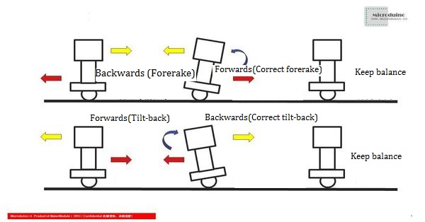
The reason why a self-balance car can keep balance is the Microduino-10DOF module with an accelerator and a gyroscope to detect the corresponding altitude data, then use Kalman algorithm to get the current of the car. The angle of the balance is 180 degrees. If the measured balance deviates from 180 degrees, the PID algorithm will adjust and output the relevant PWM values to the motor to keep the balance of the car. | The reason why a self-balance car can keep balance is the Microduino-10DOF module with an accelerator and a gyroscope to detect the corresponding altitude data, then use Kalman algorithm to get the current of the car. The angle of the balance is 180 degrees. If the measured balance deviates from 180 degrees, the PID algorithm will adjust and output the relevant PWM values to the motor to keep the balance of the car. | ||
The main code of PID: | The main code of PID: | ||
| Line 125: | Line 125: | ||
</source> | </source> | ||
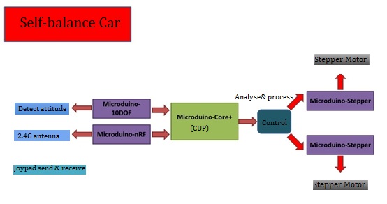
The kit makes use of a gyroscope and an acceleration sensor (Microduino-10DOF) to detect the altitude change of the car, and adopts Microduino-Stepper to adjust the motor precisely and keep balance. | The kit makes use of a gyroscope and an acceleration sensor (Microduino-10DOF) to detect the altitude change of the car, and adopts Microduino-Stepper to adjust the motor precisely and keep balance. | ||
| − | [[File: | + | [[File:1PIDtheory1.jpg||600px|center]] |
*The Main Sensor | *The Main Sensor | ||
[[Microduino-10DOF]] | [[Microduino-10DOF]] | ||
| + | |||
==Document== | ==Document== | ||
==Program Download== | ==Program Download== | ||
Revision as of 08:08, 8 January 2016
Contents[hide]Outline
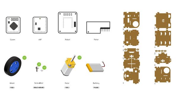
This two-wheel self-balance car is an integrated system with multiple functions, which is also a study subject focusing on automatic control theory, dynamics theory and technology theory. The essential problem is to solve self-balance and to complete tasks under various kinds of environment. In this tutorial, we adopt Microduino modules to build a self-balance car controlled by the Joypad remote controller. It enables users to play it in short time. Bill of Materials
Principle of the Experiment
PID makes difference in the automatic control area. Let's first get to know what is PID. PID refers to Proportional, Integral and Derivative. If we want the controlled object to be a steady result, we can use PID algorithm. Assuming that there is a car moves with a speed of 1m/s and we want to change that to 5m/s, we must have:
We can force the car to move until it gets to 5m/s and then withdraw the force. However, that will bring about problems as follows: 1)When the speed of the car reaches 5m/s, the device will detect the speed and notice the controller to make it change the output voltage. In that process, it takes time and in this time, the car may be accelerated more or less. 2)After withdrawing the force, outside conditions such as fraction will affect the speed of the car. However, PID algorithm can solve those problems in a certain error range. Here is how PID works. In every sampling cycle, the speed can be detected by a certain device and then transmitted into the program, and get a new speed through the program calculation. In the next sampling cycle, it'll get the new speed transmitted, then acquire a new voltage and so forth. The key of PID is how to get the car steady based on the current speed value and voltage. PID algorithm adopts proportion, integral and differential to control. Three methods correspond to a constant quantity, that is pconst, iconst and dconst respectively. These three constants are acquired under times of experiment. We can use a mathematical formula to express PID as follows: e=Expected value - input value. The reason why a self-balance car can keep balance is the Microduino-10DOF module with an accelerator and a gyroscope to detect the corresponding altitude data, then use Kalman algorithm to get the current of the car. The angle of the balance is 180 degrees. If the measured balance deviates from 180 degrees, the PID algorithm will adjust and output the relevant PWM values to the motor to keep the balance of the car. The main code of PID: // PD control.
float stabilityPDControl(float DT, float input, float setPoint, float Kp, float Kd)
{
float error;
float output;
error = setPoint - input;
// Implementation of Kd in two parts
//Only used part of the input rather than the biggest setting value of the input(T-2).
//The second one adopts the setting value.
output = Kp * error + (Kd * (setPoint - setPointOld) - Kd * (input - PID_errorOld2)) / DT;
//Serial.print(Kd*(error-PID_errorOld));Serial.print("\t");
PID_errorOld2 = PID_errorOld;
PID_errorOld = input; // The error is the only input component of the Kd value.
setPointOld = setPoint;
return(output);
}
//Realize "P" control.
float speedPControl(float input, float setPoint, float Kp)
{
float error;
error = setPoint - input;
return(Kp * error);
}The kit makes use of a gyroscope and an acceleration sensor (Microduino-10DOF) to detect the altitude change of the car, and adopts Microduino-Stepper to adjust the motor precisely and keep balance.
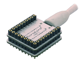
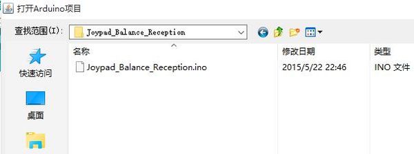
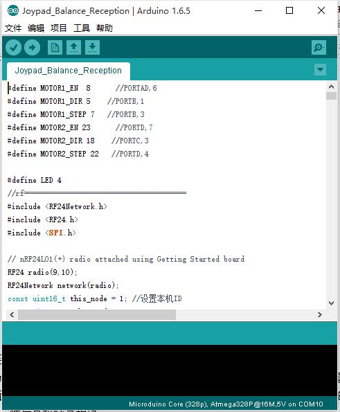
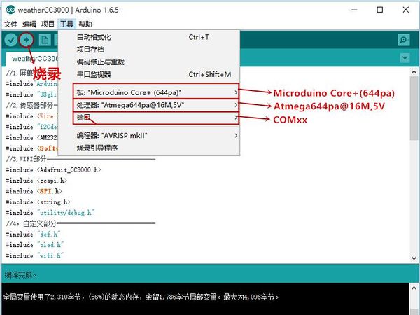
DocumentProgram DownloadStack Microduino-Core+ and Microduino-USBTTL together, then connect them to a computer with a USB cable. Make sure you build Microduino IDE. If not, please refer to 1-Arduino IDE installation instruction. Open Arduino IDE, click【File】->【Open】 Scan the project program address, click " Joypad_Balance_Reception.ino " and open. Click "Tools", select Microduino-Core+ as the board and the Atmega644pa@16M,5V as the processor. Then choose the right port and download program directly. Self-balance Car Buildup
Joypad Buildup
Joypad Debugging
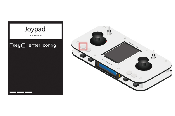
Press down Key1 within 4s after the open of the Joypad and enter Config mode.
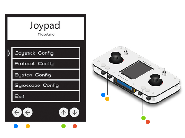
Key1- Key4 from the left to right. Please refer to the color of the picture. Note: Please enter the setting mode before the OS interface. If not, please restart and enter.
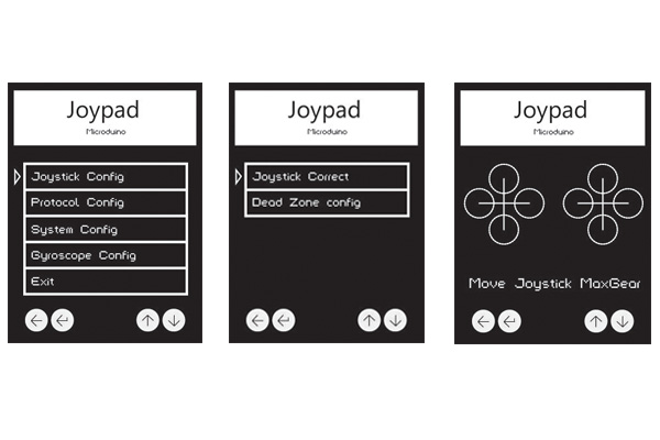
Press down Key3 and Key4 to move the cursor. The Key1 means "Return" and the Key2 means "Confirm". Select Joystick Config and enter the Joystick setting mode. Choose Joystick Correct to enter the calibration mode. A After that, it'll appear the interface shown in the third picture with an initializing state of two crosses. At the this time, you can move the joystick around. Then, you can see circles in four directions and biggest circle means the Joystick has been turned to the limit position. Press Key2 to confirm after the calibration and return to the last page.
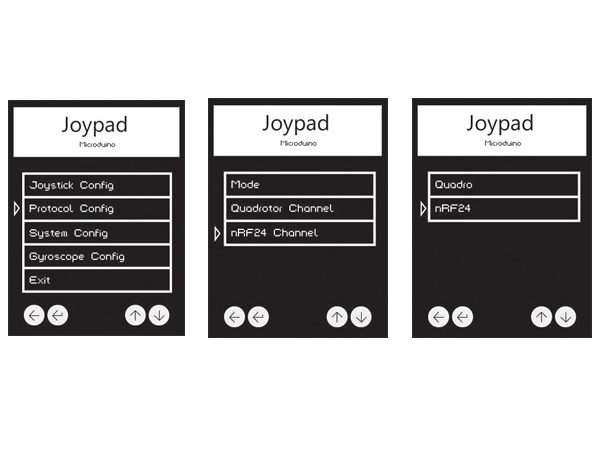
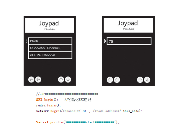
Press Key1 to return to the main page and select Protocol Config to enter mode selection. Select the first Mode, then choose nRF24(namely, Robot control mode), press Key2 to confirm and return.
Return to the secondary list, select nRF24 Channel and press Key2 to confirm. Select 70, which corresponds to the function setting of the nRF24 in Robot_Microduino.ino. Attention
Program DescriptionAddress of the baidu cloud disk: http://pan.baidu.com/s/1eQBaMjg Code:h08a Github address: https://github.com/wasdpkj/BalanceCar_Microduino/tree/master/BalanceCar_Microduino #define MOTOR_EN 4 //PORTB,0
#define MOTOR1_DIR A0 //PORTA,7
#define MOTOR1_STEP 5 //PORTB,1
#define MOTOR2_DIR A1 //PORTA,6
#define MOTOR2_STEP 6 //PORTB,2
#define MOTOR3_DIR A2 //PORTA,5
#define MOTOR3_STEP 7 //PORTB,3
#define MOTOR4_DIR A3 //PORTA,4
#define MOTOR4_STEP 8 //PORTD,6
#define LED -1
//rf=======================================
#include <RF24Network.h>
#include <RF24.h>
#include <SPI.h>
// nRF24L01(+) radio attached using Getting Started board
RF24 radio(9, 10);
RF24Network network(radio);
const uint16_t this_node = 1; //Set ID
const uint16_t other_node = 0;
//--------------------------------
struct send_a //Send
{
uint32_t node_ms; //Node running time
};
unsigned long last_sent = 0; //Timer
struct receive_a //Receive
{
uint32_t ms;
uint16_t rf_CH0;
uint16_t rf_CH1;
uint16_t rf_CH2;
uint16_t rf_CH3;
uint16_t rf_CH4;
uint16_t rf_CH5;
uint16_t rf_CH6;
uint16_t rf_CH7;
};
unsigned long clock; //Host machine running time
int tem_xuan = 0; //Host machine request schedule
//----------------------------
boolean node_STA = false;
unsigned long safe_ms = millis();
//=================================================================================
#include <Wire.h>
#include <I2Cdev.h>
#include <JJ_MPU6050_DMP_6Axis.h> // DMP working library's revised version.
//=================================================================================
#define CLR(x,y) (x&=(~(1<<y)))
#define SET(x,y) (x|=(1<<y))
//=========================================
#define DEBUG 0
#define ZERO_SPEED 65535 //Zero speed
#define MAX_ACCEL 7 //The maximum ACCEL
#define MAX_THROTTLE 480 //The maximum throttle is 530.
#define MAX_STEERING 120 //The maximum steering
#define MAX_TARGET_ANGLE 15 //The maximum target is 12.
// Default control items
#define ANGLE_FIX -3.5
#define KP 0.22 // 0.22
#define KD 28 // 30 28 26
#define KP_THROTTLE 0.065 //0.08//0.065
#define KI_THROTTLE 0.05//0.05
// For "raiseup" control gains.
#define KP_RAISEUP 0.02 //kp raise up
#define KD_RAISEUP 40 //kd raise up
#define KP_THROTTLE_RAISEUP 0 //No speed control on "raiseup"
#define KI_THROTTLE_RAISEUP 0.0//Throttle raise up
#define ITERM_MAX_ERROR 40 // ITERM saturation constant
#define ITERM_MAX 5000
//=================================================================================
#define I2C_SPEED 400000L //I2C speed
#define Gyro_Gain 0.03048//Gyroscope gain
#define Gyro_Scaled(x) x*Gyro_Gain //Return the original data of the gyroscope
#define RAD2GRAD 57.2957795//57.2957795
#define GRAD2RAD 0.01745329251994329576923690768489//0.01745329251994329576923690768489
//=================================================================================
bool Robot_shutdown = false; // Robot shutdown flag => Out of battery
uint8_t mode; // 0: MANUAL MODE 1: autonomous MODE
uint8_t autonomous_mode_status; // 1: NORMAL STATUS=Walking 2:
int16_t autonomous_mode_counter;
int16_t autonomous_mode_distance;
int16_t pushUp_counter; // for pushUp functionality (experimental)
// MPU Control/Status
bool dmpReady = false; // Set as True if DMP initialization is ready.
uint8_t mpuIntStatus; // Own MPU interruption status bytes
uint8_t devStatus; // Each deveice will return to the original status after operation. (0=Ready! 0=False)
uint16_t packetSize; // Predict DMP packet(Here is 18 bytes.
uint16_t fifoCount; // All bytes in FIFO.
uint8_t fifoBuffer[18]; // FIFO buffer
Quaternion q;
uint8_t loop_counter; // Generate 40Hz loop
uint8_t slow_loop_counter; // Slow loop 2HZ
long timer_old;//Old timer
long timer_value;//Timer value
int debug_counter;//Debug the counter
float dt;
int lkf;
// The default I2C daddress is 0X68
MPU6050 mpu;
float angle_adjusted;//Angle adjustment
float angle_adjusted_Old;// Angle adjustment
float Kp = KP;
float Kd = KD;
float Kp_thr = KP_THROTTLE; //Throttle
float Ki_thr = KI_THROTTLE;
float Kp_user = KP;
float Kd_user = KD;
float Kp_thr_user = KP_THROTTLE;
float Ki_thr_user = KI_THROTTLE;
bool newControlParameters = false;//New Bool control parameters
bool modifing_control_parameters = false; // New Bool control parameters
float PID_errorSum;
float PID_errorOld = 0;
float PID_errorOld2 = 0;
float setPointOld = 0;
float target_angle;
float throttle;
float kkll;
float steering;
float max_throttle = MAX_THROTTLE;//
float max_steering = MAX_STEERING;
float max_target_angle = MAX_TARGET_ANGLE;
float control_output;
int16_t motor1;
int16_t motor2;
int16_t speed_m[2]; // Actual motor rotation speed
uint8_t dir_m[2]; // Actual rotation direction of the stepper motor
int16_t actual_robot_speed; // Actual robot speed
int16_t actual_robot_speed_Old; // Actual robot speed
float estimated_speed_filtered;//Filtered estimated speed
uint16_t counter_m[2]; // Cycle of the counter
uint16_t period_m[2][8]; //
uint8_t period_m_index[2]; //
int freeRam () { //Free Ram
extern int __heap_start, *__brkval;
int v;
return (int) &v - (__brkval == 0 ? (int) &__heap_start : (int) __brkval);
}
//DMP Function
//This function defines the weight on the accelerated sensor.
//0x80 by default
//The official name of InvenSense is inv_key_0_96(?)
void dmpSetSensorFusionAccelGain(uint8_t gain) {
// INV_KEY_0_96
mpu.setMemoryBank(0);
mpu.setMemoryStartAddress(0x60);
mpu.writeMemoryByte(0);
mpu.writeMemoryByte(gain);
mpu.writeMemoryByte(0);
mpu.writeMemoryByte(0);
}
// Calculate and get Obtein angle
float dmpGetPhi() {
mpu.getFIFOBytes(fifoBuffer, 16); // Get FIFO bytes
mpu.dmpGetQuaternion(&q, fifoBuffer);
mpu.resetFIFO(); //Reset FIFO
//Return ( asin(-2*(q.x * q.z - q.w * q.y)) * 180/M_PI); //roll
return (atan2(2 * (q.z * q.y + q.x * q.w), q.x * q.x - q.w * q.w - q.z * q.z + q.y * q.y) * RAD2GRAD);
}
//xyzw
//wzyx
// PD's implementation. DT is "ms".
float stabilityPDControl(float DT, float input, float setPoint, float Kp, float Kd)
{
float error;
float output;
error = setPoint - input;
// Implementation of Kd's two parts
//Only adopt parts of the sensor input ranther than the maximum set value (T-2).
//However, the second adopts that set value.
output = Kp * error + (Kd * (setPoint - setPointOld) - Kd * (input - PID_errorOld2)) / DT; // + Erro - PID_error_Old2
//Serial.print(Kd*(error-PID_errorOld));Serial.print("\t");
PID_errorOld2 = PID_errorOld;
PID_errorOld = input; // Error is the only input component of Kd.
setPointOld = setPoint;
return (output);
}
//P control realizes.
float speedPControl(float input, float setPoint, float Kp)
{
float error;
error = setPoint - input;
return (Kp * error);
}
// PI realizes; DT is "ms".
float speedPIControl(float DT, float input, float setPoint, float Kp, float Ki)
{
float error;
float output;
error = setPoint - input;
PID_errorSum += constrain(error, -ITERM_MAX_ERROR, ITERM_MAX_ERROR);
PID_errorSum = constrain(PID_errorSum, -ITERM_MAX, ITERM_MAX);
output = Kp * error + Ki * PID_errorSum * DT * 0.001;
return (output);
}
void calculateSubperiods(uint8_t motor)
{
int subperiod;
int absSpeed;
uint8_t j;
if (speed_m[motor] == 0)
{
for (j = 0; j < 8; j++)
period_m[motor][j] = ZERO_SPEED;
return;
}
if (speed_m[motor] > 0 ) // Positive speed
{
dir_m[motor] = 1;
absSpeed = speed_m[motor];
}
else // Negative speed
{
dir_m[motor] = 0;
absSpeed = -speed_m[motor];
}
for (j = 0; j < 8; j++)
period_m[motor][j] = 1000 / absSpeed;
// Calculate subage. If module <0.25=>sub-period= 0. If module<0.75 sub-period=2
If module <0.5=>sub-period= 1. If module <0.75 sub-period=2 other sub-periods =3
subperiod = ((1000 % absSpeed) * 8) / absSpeed; // Optimize code to calculate the sub-period. (Integer arithmetic)
if (subperiod > 0)
period_m[motor][1]++;
if (subperiod > 1)
period_m[motor][5]++;
if (subperiod > 2)
period_m[motor][3]++;
if (subperiod > 3)
period_m[motor][7]++;
if (subperiod > 4)
period_m[motor][0]++;
if (subperiod > 5)
period_m[motor][4]++;
if (subperiod > 6)
period_m[motor][2]++;
}
void setMotorSpeed(uint8_t motor, int16_t tspeed)
{
// We limite the maximum speed
if ((speed_m[motor] - tspeed) > MAX_ACCEL)
speed_m[motor] -= MAX_ACCEL;
else if ((speed_m[motor] - tspeed) < -MAX_ACCEL)
speed_m[motor] += MAX_ACCEL;
else
speed_m[motor] = tspeed;
calculateSubperiods(motor); //We adopt four sub-periods to enhance resolution.
// Save energy and don't run it.
if ((speed_m[0] == 0) && (speed_m[1] == 0))
{
digitalWrite(MOTOR_EN, HIGH); //Don't use the motor
}
else
{
digitalWrite(MOTOR_EN, LOW); // Use the motor
}
}
void setup()
{
Serial.begin(115200);
// Stepper pins
pinMode(MOTOR_EN, OUTPUT); // ENABLE MOTORS
pinMode(MOTOR1_DIR, OUTPUT); // DIR MOTOR 1
pinMode(MOTOR1_STEP, OUTPUT); // STEP MOTOR 1
pinMode(MOTOR4_DIR, OUTPUT); // DIR MOTOR 4
pinMode(MOTOR4_STEP, OUTPUT); // STEP MOTOR 4
digitalWrite(MOTOR_EN, HIGH); // Disbale motors
pinMode(LED, OUTPUT); // ENABLE MOTORS
//mpu==============================
// Add in I2C bus
Wire.begin();
// 4000Khz fast mode
TWSR = 0;
TWBR = ((16000000L / I2C_SPEED) - 16) / 2;
TWCR = 1 << TWEN;
digitalWrite(LED, HIGH);
delay(200);
digitalWrite(LED, LOW);
delay(200);
Serial.println("Initializing I2C devices...");
//mpu.initialize();
mpu.setClockSource(MPU6050_CLOCK_PLL_ZGYRO);
mpu.setFullScaleGyroRange(MPU6050_GYRO_FS_2000);
mpu.setFullScaleAccelRange(MPU6050_ACCEL_FS_2);
mpu.setDLPFMode(MPU6050_DLPF_BW_20); //10,20,42,98,188
mpu.setRate(4); // 0=1khz 1=500hz, 2=333hz, 3=250hz 4=200hz
mpu.setSleepEnabled(false);
digitalWrite(LED, HIGH);
delay(500);
digitalWrite(LED, LOW);
delay(500);
Serial.println(F("Initializing DMP..."));
devStatus = mpu.dmpInitialize();
if (devStatus == 0)
{
// turn on the DMP, now that it's ready
Serial.println(F("Enabling DMP..."));
mpu.setDMPEnabled(true);
mpuIntStatus = mpu.getIntStatus();
dmpReady = true;
digitalWrite(LED, HIGH);
delay(200);
digitalWrite(LED, LOW);
delay(200);
}
else
{ // ERROR!
while (1)
{
// 1 = initial memory load failed
// 2 = DMP configuration updates failed
// (if it's going to break, usually the code will be 1)
Serial.print(F("DMP Initialization failed (code "));
Serial.print(devStatus);
Serial.println(F(")"));
digitalWrite(LED, HIGH);
delay(1000);
digitalWrite(LED, LOW);
delay(200);
}
}
// Calibration of the gyroscope
//The robotmust be steady when initializing.
// It needs to reset and calibrate the gyroscope.
digitalWrite(LED, HIGH);
delay(200);
digitalWrite(LED, LOW);
delay(500);
digitalWrite(LED, HIGH);
delay(200);
digitalWrite(LED, LOW);
Serial.print("Free RAM: ");
Serial.println(freeRam());
Serial.print("Max_throttle: ");
Serial.println(max_throttle);
Serial.print("Max_steering: ");
Serial.println(max_steering);
Serial.print("Max_target_angle: ");
Serial.println(max_target_angle);
// verify connection
Serial.println("Testing device connections...");
Serial.println(mpu.testConnection() ? "MPU6050 connection successful" : "MPU6050 connection failed");
timer_old = millis();
TIMER_INT();
//Adjust DMP sensor fusion
Serial.println("Adjusting DMP sensor fusion gain...");
dmpSetSensorFusionAccelGain(0x40);//0x20///////////////////////////////Adjust the sensor
Serial.println("Initializing Stepper motors...");
digitalWrite(MOTOR_EN, LOW); // Stepper driver
// The vibration of the motor indicates the robot is ready.
for (uint8_t k = 0; k < 3; k++)
{
setMotorSpeed(0, 3);
setMotorSpeed(1, -3);
delay(150);
setMotorSpeed(0, -3);
setMotorSpeed(1, 3);
delay(150);
}
mpu.resetFIFO();
timer_old = millis();
//nRF==============================
SPI.begin(); //Initialize SPI bus
radio.begin();
network.begin(/*channel*/ 70, /*node address*/ this_node);
digitalWrite(LED, HIGH);
Serial.println("===========start===========");
}
// Major loop//////////////////////////////////////////////////////////////////////////
void loop()
{
//===============================================================
if (nRF(&throttle, &steering))
{
/*
Serial.print(Speed_need);
Serial.print(",");
Serial.println(Turn_need);
*/
}
//===============================================================
if (safe_ms > millis()) safe_ms = millis();
if (millis() - safe_ms > 1000)
{
steering = 0;
throttle = 0;
}
//===============================================================
robot();
}
void robot()
{
//===============================================================
timer_value = millis();
// New DMP positioning solution
fifoCount = mpu.getFIFOCount();
if (fifoCount >= 18)
{
if (fifoCount > 18) // If we have one or more data packets, we can adopt the simplest way to dump the buffer zone.
{
mpu.resetFIFO();
return;
}
loop_counter++;
slow_loop_counter++;
dt = (timer_value - timer_old);
timer_old = timer_value;
angle_adjusted_Old = angle_adjusted;
angle_adjusted = dmpGetPhi() + ANGLE_FIX;
Serial.println(angle_adjusted);
mpu.resetFIFO(); // Rest FIFO
// Calculate and estimate the robot speed
actual_robot_speed_Old = actual_robot_speed;
actual_robot_speed = (speed_m[1] - speed_m[0]) / 2; // Front
// Angle adjusted
int16_t angular_velocity = (angle_adjusted - angle_adjusted_Old) * 90.0;
// Use the robot speed (T-1) or (T-2) to compensate the delay
int16_t estimated_speed = actual_robot_speed_Old - angular_velocity;
//Estimated speed
estimated_speed_filtered = estimated_speed_filtered * 0.95 + (float)estimated_speed * 0.05;
//Target angle
target_angle = speedPIControl(dt, estimated_speed_filtered, throttle, Kp_thr, Ki_thr);
//Limited output
target_angle = constrain(target_angle, -max_target_angle, max_target_angle);
if (pushUp_counter > 0) // pushUp mode?
target_angle = 10;
//Integrate output acceleration
control_output += stabilityPDControl(dt, angle_adjusted, target_angle, Kp, Kd);
control_output = constrain(control_output, -800, 800); // Limite the maxiumum output control
// Control steering output
motor1 = control_output + steering;
motor2 = -control_output + steering; //Motor2 rotates conversely.
// Limit the maximum speed
motor1 = constrain(motor1, -500, 500);
motor2 = constrain(motor2, -500, 500);
// Is robot ready (upright?)
if ((angle_adjusted < 66) && (angle_adjusted > -66))
{
if (node_STA) // pushUp mode?
{
pushUp_counter++;
if (pushUp_counter > 60) // 0.3 seconds
{
// Set motors to 0 => disable steppers => robot
setMotorSpeed(0, 0);
setMotorSpeed(1, 0);
// We prepare the raiseup mode
Kp = KP_RAISEUP; // CONTROL GAINS FOR RAISE UP
Kd = KD_RAISEUP;
Kp_thr = KP_THROTTLE_RAISEUP;
control_output = 0;
estimated_speed_filtered = 0;
}
else
{
setMotorSpeed(0, motor1);
setMotorSpeed(1, motor2);
}
}
else
{
// NORMAL MODE
setMotorSpeed(0, motor1);
setMotorSpeed(1, motor2);
pushUp_counter = 0;
}
if ((angle_adjusted < 40) && (angle_adjusted > -40))
{
Kp = Kp_user; // Default or user control gains
Kd = Kd_user;
Kp_thr = Kp_thr_user;
Ki_thr = Ki_thr_user;
}
else
{
Kp = KP_RAISEUP; // CONTROL GAINS FOR RAISE UP
Kd = KD_RAISEUP;
Kp_thr = KP_THROTTLE_RAISEUP;
Ki_thr = KI_THROTTLE_RAISEUP;
}
}
else // Robot not ready, angle > 70º
{
setMotorSpeed(0, 0);
setMotorSpeed(1, 0);
PID_errorSum = 0; // Reset PID I term
Kp = KP_RAISEUP; // CONTROL GAINS FOR RAISE UP
Kd = KD_RAISEUP;
Kp_thr = KP_THROTTLE_RAISEUP;
Ki_thr = KI_THROTTLE_RAISEUP;
}
}
}
boolean nRF(float * _speed, float * _turn)
{
network.update();
// Is there anything ready for us?
while ( network.available() )
{
// If so, grab it and print it out
RF24NetworkHeader header;
receive_a rec;
network.read(header, &rec, sizeof(rec));
clock = rec.ms; //Receive the assigned running time values of the host machine.
float * _i = _speed;
_i[0] = map(rec.rf_CH1, 1000, 2000, -MAX_THROTTLE, MAX_THROTTLE);
_i = _turn;
_i[0] = map(rec.rf_CH0, 1000, 2000, -MAX_STEERING, MAX_STEERING);
node_STA = (rec.rf_CH7 > 1500 ? true : false); //Receive the assigned
request schedule values
{
//Serial.print("Sending...");
send_a sen = {
millis()
}; //Send out the data corresponding to the previous sending array.
RF24NetworkHeader header(0);
boolean ok = network.write(header, &sen, sizeof(sen));
safe_ms = millis();
if (ok)
{
return true;
//Serial.println("ok.");
}
else
{
return false;
//Serial.println("failed.");
}
}
safe_ms = millis();
}
}Joypad Program and DescriptionJoypad_RC.ino #include "Arduino.h"
#include "def.h"
#include "time.h"
#include "bat.h"
#if defined(__AVR_ATmega1284P__) || defined(__AVR_ATmega644P__) || defined(__AVR_ATmega128RFA1__)
#include "mpu.h"
#endif
#include "joy.h"
#include "key.h"
#include "data.h"
#include "nrf.h"
#include "mwc.h"
#include "tft.h"
#include "eep.h"
#if defined(__AVR_ATmega128RFA1__)
#include <ZigduinoRadio.h>
#endif
//joypad================================
#include <Joypad.h>
//eeprom================================
#include <EEPROM.h>
//TFT===================================
#include <Adafruit_GFX.h> // Core graphics library
#include <Adafruit_ST7735.h> // Hardware-specific
#include <SPI.h>
//rf====================================
#include <RF24Network.h>
#include <RF24.h>
#if defined(__AVR_ATmega1284P__) || defined(__AVR_ATmega644P__) || defined(__AVR_ATmega128RFA1__)
//MPU===================================
#include "Wire.h"
#include "I2Cdev.h"
#include "MPU6050_6Axis_MotionApps20.h"
#endif
//spi===================================
#include <SPI.h>
void setup()
{
// initialize serial communication at 115200 bits per second:
#ifdef Serial_DEBUG
Serial.begin(115200);
delay(100);
Serial.println("========hello========");
#endif
//---------------
key_init();
//---------------
#ifdef Serial_DEBUG
Serial.println("\n\r EEPROM READ...");
#endif
eeprom_read();
//---------------
#ifdef Serial_DEBUG
Serial.println("\n\r TFT INIT...");
#endif
TFT_init(true, tft_rotation);
//---------------
#ifdef Serial_DEBUG
Serial.println("\n\r TFT BEGIN...");
#endif
TIME1 = millis();
while (millis() - TIME1 < interval_TIME1)
{
TFT_begin();
if (!Joypad.readButton(CH_SWITCH_1))
{
#ifdef Serial_DEBUG
Serial.println("\n\rCorrect IN...");
#endif
//---------------
#ifdef Serial_DEBUG
Serial.println("\n\r TFT INIT...");
#endif
TFT_init(false, tft_rotation);
while (1)
{
if (!TFT_config())
break;
}
#ifdef Serial_DEBUG
Serial.println("\n\rCorrect OUT...");
#endif
//---------------
#ifdef Serial_DEBUG
Serial.println("\n\r EEPROM WRITE...");
#endif
eeprom_write();
}
}
//---------------
#ifdef Serial_DEBUG
Serial.println("\n\r TFT CLEAR...");
#endif
TFT_clear();
//---------------
#ifdef Serial_DEBUG
Serial.println("\n\r TFT READY...");
#endif
TFT_ready();
//---------------.l
if (mode_protocol) //Robot
{
SPI.begin(); //Initialize SPI
radio.begin();
network.begin(/*channel*/ nrf_channal, /*node address*/ this_node);
}
else //QuadCopter
{
unsigned long _channel;
#if !defined(__AVR_ATmega128RFA1__)
switch (mwc_channal)
{
case 0:
_channel = 9600;
break;
case 1:
_channel = 19200;
break;
case 2:
_channel = 38400;
break;
case 3:
_channel = 57600;
break;
case 4:
_channel = 115200;
break;
}
#else if
_channel = mwc_channal;
#endif
mwc_port.begin(_channel);
}
//---------------
#ifdef Serial_DEBUG
Serial.println("===========start===========");
#endif
#if defined(__AVR_ATmega1284P__) || defined(__AVR_ATmega644P__) || defined(__AVR_ATmega128RFA1__)
if (mode_mpu) initMPU(); //initialize device
#endif
}
void loop()
{
// unsigned long time = millis();
#if defined(__AVR_ATmega1284P__) || defined(__AVR_ATmega644P__) || defined(__AVR_ATmega128RFA1__)
//MPU--------------------------------
if (mode_mpu)
getMPU();
#endif
//DATA_begin------------------------------
data_begin();
//DATA_send-------------------------------
if (millis() < time2) time2 = millis();
if (millis() - time2 > interval_time2)
{
if (mode_protocol) nrf_send(); //Robot
else data_send(); //QuadCopter
time2 = millis();
}
//Node checking -------------------------------
vodebug();
//BAT--------------------------------
if (time3 > millis()) time3 = millis();
if (millis() - time3 > interval_time3)
{
vobat();
time3 = millis();
}
//TFT------------------------------------
TFT_run();
//===================================
// time = millis() - time;
// Serial.println(time, DEC); //loop time
}
</cpp>
BAT.h
<source lang="cpp">
int8_t _V_bat = _V_min;
boolean mcu_voltage = true; // 5.0 or 3.3
#define _V_fix 0.2 //fix battery voltage
#define _V_math(Y) (_V_fix+((Y*analogRead(PIN_bat)/1023.0f)/(33.0f/(51.0f+33.0f))))
void vobat()
{
//_V_bat=10*((voltage*analogRead(PIN_bat)/1023.0f)/(33.0f/(51.0f+33.0f)));
_V_bat = _V_math(mcu_voltage ? 50 : 33);
_V_bat = constrain(_V_bat, _V_min, _V_max);
#ifdef Serial_DEBUG
Serial.print("_V_bat: ");
Serial.println(_V_bat);
#endif
}data.h #include "Arduino.h"
byte inBuf[16];
int16_t outBuf[8] =
{
Joy_MID, Joy_MID, Joy_MID, Joy_MID, Joy_MID, Joy_MID, Joy_MID, Joy_MID
};
boolean AUX[4] = {0, 0, 0, 0};
//======================================
void data_begin()
{
Joy();
if (mode_protocol) //Robot
{
if (!sw_l)
{
Joy_x = Joy_MID;
Joy_y = Joy_MID;
Joy1_x = Joy_MID;
Joy1_y = Joy_MID;
}
}
else //QuadCopter
{
if (!sw_l)
Joy_y = Joy_MID - Joy_maximum;
}
//but---------------------------------
for (uint8_t a = 0; a < 4; a++)
{
if (key_get(a, 1)) AUX[a] = !AUX[a];
}
outBuf[0] = Joy1_x;
outBuf[1] = Joy1_y;
outBuf[2] = Joy_x;
outBuf[3] = Joy_y;
outBuf[4] = map(AUX[0], 0, 1, Joy_MID - Joy_maximum, Joy_MID + Joy_maximum);
outBuf[5] = map(AUX[1], 0, 1, Joy_MID - Joy_maximum, Joy_MID + Joy_maximum);
outBuf[6] = map(AUX[2], 0, 1, Joy_MID - Joy_maximum, Joy_MID + Joy_maximum);
outBuf[7] = map(AUX[3], 0, 1, Joy_MID - Joy_maximum, Joy_MID + Joy_maximum);
}def.h #include "Arduino.h"
//DEBUG-----------
#define Serial_DEBUG
//MWC-------------
uint8_t mwc_channal = 11; //RF channel
#if defined(__AVR_ATmega32U4__)
#define mwc_port Serial1 //Serial1 is D0 D1
#elif defined(__AVR_ATmega128RFA1__)
#define mwc_port ZigduinoRadio //RF
#else
#define mwc_port Serial //Serial is D0 D1
#endif
//nRF-------------
#define interval_debug 2000 //Node checking interval.
uint8_t nrf_channal = 70; //0~125
//Battery---------
#define PIN_bat A7 //BAT
#define _V_max 41 //The maximum voltage of the Li-ion battery is 4.2V
#define _V_min 36 // The minimum voltage of the Li-ion battery is 3.7
#if defined(__AVR_ATmega1284P__) || defined(__AVR_ATmega644P__) || defined(__AVR_ATmega128RFA1__)
//MPU-------------
#define MPU_maximum 70
#endif
//Time------------
#define interval_TIME1 2000 //setup delay
#define interval_time2 40 //send interval
#define interval_time3 1000 //battery intervaleep.h #include "Arduino.h"
#include <EEPROM.h>
#define EEPROM_write(address, p) {int i = 0; byte *pp = (byte*)&(p);for(; i < sizeof(p); i++) EEPROM.write(address+i, pp[i]);}
#define EEPROM_read(address, p) {int i = 0; byte *pp = (byte*)&(p);for(; i < sizeof(p); i++) pp[i]=EEPROM.read(address+i);}
struct config_type
{
int16_t eeprom_correct_min[4];
int16_t eeprom_correct_max[4];
uint8_t eeprom_Joy_deadzone_val;
#if defined(__AVR_ATmega1284P__) || defined(__AVR_ATmega644P__) || defined(__AVR_ATmega128RFA1__)
boolean eeprom_mode_mpu;
#endif
boolean eeprom_mode_protocol;
uint8_t eeprom_mwc_channal;
uint8_t eeprom_nrf_channal;
boolean eeprom_tft_theme;
boolean eeprom_tft_rotation;
boolean eeprom_mcu_voltage;
};
//======================================
void eeprom_read()
{
//EEPROM reads assigned values.
config_type config_readback;
EEPROM_read(0, config_readback);
for (uint8_t a = 0; a < 4; a++)
{
joy_correct_min[a] = config_readback.eeprom_correct_min[a];
joy_correct_max[a] = config_readback.eeprom_correct_max[a];
}
Joy_deadzone_val = config_readback.eeprom_Joy_deadzone_val;
mode_protocol = config_readback.eeprom_mode_protocol;
#if defined(__AVR_ATmega1284P__) || defined(__AVR_ATmega644P__) || defined(__AVR_ATmega128RFA1__)
mode_mpu = config_readback.eeprom_mode_mpu;
#endif
mwc_channal = config_readback.eeprom_mwc_channal;
nrf_channal = config_readback.eeprom_nrf_channal;
tft_theme = config_readback.eeprom_tft_theme;
tft_rotation = config_readback.eeprom_tft_rotation;
mcu_voltage = config_readback.eeprom_mcu_voltage;
}
void eeprom_write()
{
// Define structure variable config and its content
config_type config;
for (uint8_t a = 0; a < 4; a++)
{
config.eeprom_correct_min[a] = joy_correct_min[a];
config.eeprom_correct_max[a] = joy_correct_max[a];
}
config.eeprom_Joy_deadzone_val = Joy_deadzone_val;
config.eeprom_mode_protocol = mode_protocol;
#if defined(__AVR_ATmega1284P__) || defined(__AVR_ATmega644P__) || defined(__AVR_ATmega128RFA1__)
config.eeprom_mode_mpu = mode_mpu;
#endif
config.eeprom_mwc_channal = mwc_channal;
config.eeprom_nrf_channal = nrf_channal;
config.eeprom_tft_theme = tft_theme;
config.eeprom_tft_rotation = tft_rotation;
config.eeprom_mcu_voltage = mcu_voltage;
// Save the variable config into EEPROM written with address 0.
EEPROM_write(0, config);
}joy.h #include "Arduino.h"
#include <Joypad.h>
//Joy-------------
//1000~2000
uint8_t Joy_deadzone_val = 10;
#define Joy_s_maximum 200 //MAX 300
#define Joy_maximum 450 //MAX 500
#define Joy_MID 1500 //1500
boolean mode_mpu, mode_protocol; //{(0: 0 is mwc, 1 is nrf),(1: 0 is mpu, 1 is no mpu)}
int16_t joy_correct_max[4], joy_correct_min[4];
int16_t Joy_x, Joy_y, Joy1_x, Joy1_y;
int16_t s_lig, s_mic;
boolean Joy_sw, Joy1_sw;
boolean but1, but2, but3, but4;
boolean sw_l, sw_r;
//======================================
int16_t Joy_dead_zone(int16_t _Joy_vol)
{
if (abs(_Joy_vol) > Joy_deadzone_val)
return ((_Joy_vol > 0) ? (_Joy_vol - Joy_deadzone_val) : (_Joy_vol + Joy_deadzone_val));
else
return 0;
}
int16_t Joy_i(int16_t _Joy_i, boolean _Joy_b, int16_t _Joy_MIN, int16_t _Joy_MAX)
{
int16_t _Joy_a;
switch (_Joy_i)
{
case 0:
_Joy_a = Joy_dead_zone(Joypad.readJoystickX());
break;
case 1:
_Joy_a = Joypad.readJoystickY(); //throt
break;
case 2:
_Joy_a = Joy_dead_zone(Joypad.readJoystick1X());
break;
case 3:
_Joy_a = Joy_dead_zone(Joypad.readJoystick1Y());
break;
}
if (_Joy_b)
{
if (_Joy_a < 0)
_Joy_a = map(_Joy_a, joy_correct_min[_Joy_i], 0, _Joy_MAX, Joy_MID);
else
_Joy_a = map(_Joy_a, 0, joy_correct_max[_Joy_i], Joy_MID, _Joy_MIN);
if (_Joy_a < _Joy_MIN) _Joy_a = _Joy_MIN;
if (_Joy_a > _Joy_MAX) _Joy_a = _Joy_MAX;
}
return _Joy_a;
}
void Joy()
{
sw_l = Joypad.readButton(CH_SWITCH_L);
sw_r = Joypad.readButton(CH_SWITCH_R);
//------------------------------------
//s_lig=Joypad.readLightSensor();
//s_mic=Joypad.readMicrophone();
//------------------------------------
Joy_sw = Joypad.readButton(CH_JOYSTICK_SW);
Joy1_sw = Joypad.readButton(CH_JOYSTICK1_SW);
//------------------------------------
but1 = Joypad.readButton(CH_SWITCH_1);
but2 = Joypad.readButton(CH_SWITCH_2);
but3 = Joypad.readButton(CH_SWITCH_3);
but4 = Joypad.readButton(CH_SWITCH_4);
#if defined(__AVR_ATmega1284P__) || defined(__AVR_ATmega644P__) || defined(__AVR_ATmega128RFA1__)
//====================================
int16_t y[3]; //MPU---------------------------------
if (mode_mpu) //MPU---------------------------------
{
for (uint8_t a = 0; a < 3; a++)
{
y[a] = ypr[a] * 180 / M_PI;
if (y[a] > MPU_maximum) y[a] = MPU_maximum;
if (y[a] < -MPU_maximum) y[a] = -MPU_maximum;
}
}
#endif
if (Joypad.readButton(CH_SWITCH_R))
{
Joy_x = Joy_i(0, true, Joy_MID - Joy_maximum, Joy_MID + Joy_maximum);
Joy_y = Joy_i(1, true, Joy_MID - Joy_maximum, Joy_MID + Joy_maximum);
#if defined(__AVR_ATmega1284P__) || defined(__AVR_ATmega644P__) || defined(__AVR_ATmega128RFA1__)
if (mode_mpu) //MPU---------------------------------
{
Joy1_x = map(y[2], -MPU_maximum, MPU_maximum, Joy_MID - Joy_maximum, Joy_MID + Joy_maximum);
Joy1_y = map(y[1], -MPU_maximum, MPU_maximum, Joy_MID - Joy_maximum, Joy_MID + Joy_maximum);
}
else
#endif
{
Joy1_x = Joy_i(2, true, Joy_MID - Joy_maximum, Joy_MID + Joy_maximum);
Joy1_y = Joy_i(3, true, Joy_MID - Joy_maximum, Joy_MID + Joy_maximum);
}
}
else
{
Joy_x = Joy_i(0, true, Joy_MID - Joy_s_maximum, Joy_MID + Joy_s_maximum);
Joy_y = Joy_i(1, true, mode_protocol ? Joy_MID - Joy_s_maximum : Joy_MID - Joy_maximum, mode_protocol ? Joy_MID
+ Joy_s_maximum : Joy_MID + Joy_maximum); // Robot,QuadCopter
#if defined(__AVR_ATmega1284P__) || defined(__AVR_ATmega644P__) || defined(__AVR_ATmega128RFA1__)
if (mode_mpu) //MPU---------------------------------
{
Joy1_x = map(y[2], -MPU_maximum, MPU_maximum, Joy_MID - Joy_s_maximum, Joy_MID + Joy_s_maximum);
Joy1_y = map(y[1], -MPU_maximum, MPU_maximum, Joy_MID - Joy_s_maximum, Joy_MID + Joy_s_maximum);
}
else
#endif
{
Joy1_x = Joy_i(2, true, Joy_MID - Joy_s_maximum, Joy_MID + Joy_s_maximum);
Joy1_y = Joy_i(3, true, Joy_MID - Joy_s_maximum, Joy_MID + Joy_s_maximum);
}
}
}key.h #include "arduino.h"
uint8_t key_pin[4] = {CH_SWITCH_1, CH_SWITCH_2, CH_SWITCH_3, CH_SWITCH_4}; //Key1,Key2, Key3 and Key4
boolean key_status[4]; //Key
boolean key_cache[4]; //Detect key cache when loosening it.
void key_init()
{
for (uint8_t a = 0; a < 4; a++)
{
key_status[a] = LOW;
key_cache[a] = HIGH;
}
}
boolean key_get(uint8_t _key_num, boolean _key_type)
{
key_cache[_key_num] = key_status[_key_num]; //Judge from the cache
key_status[_key_num] = !Joypad.readButton(key_pin[_key_num]); //When triggering
switch (_key_type)
{
case 0:
if (!key_status[_key_num] && key_cache[_key_num]) // After pressing down and loosening
return true;
else
return false;
break;
case 1:
if (key_status[_key_num] && !key_cache[_key_num]) // After pressing down and loosening
return true;
else
return false;
break;
}
}mpu.h #if defined(__AVR_ATmega1284P__) || defined(__AVR_ATmega644P__) || defined(__AVR_ATmega128RFA1__)
#include "Wire.h"
#include "I2Cdev.h"
#include "MPU6050_6Axis_MotionApps20.h"
MPU6050 mpu;
//MPU-------------
#define MPU_maximum 70
// MPU control/status vars
boolean dmpReady = false; // set true if DMP init was successful
uint8_t mpuIntStatus; // holds actual interrupt status byte from MPU
uint8_t devStatus; // return status after each device operation (0 = success, !0 = error)
uint16_t packetSize; // expected DMP packet size (default is 42 bytes)
uint16_t fifoCount; // count of all bytes currently in FIFO
uint8_t fifoBuffer[64]; // FIFO storage buffer
// orientation/motion vars
Quaternion q; // [w, x, y, z] quaternion container
VectorInt16 aa; // [x, y, z] accel sensor measurements
VectorFloat gravity; // [x, y, z] gravity vector
float ypr[3]; // [yaw, pitch, roll] yaw/pitch/roll container and gravity vector
void initMPU()
{
Wire.begin();
#ifdef Serial_DEBUG
Serial.println(F("Initializing I2C devices..."));
#endif
mpu.initialize();
// verify connection
#ifdef Serial_DEBUG
Serial.println(F("Testing device connections..."));
#endif
if (mpu.testConnection())
{
#ifdef Serial_DEBUG
Serial.println("MPU6050 connection successful");
#endif
}
#ifdef Serial_DEBUG
else
Serial.println(F("MPU6050 connection failed"));
#endif
// load and configure the DMP
#ifdef Serial_DEBUG
Serial.println(F("Initializing DMP..."));
#endif
devStatus = mpu.dmpInitialize();
// make sure it worked (returns 0 if so)
if (devStatus == 0) {
// turn on the DMP, now that it's ready
#ifdef Serial_DEBUG
Serial.println(F("Enabling DMP..."));
#endif
mpu.setDMPEnabled(true);
mpuIntStatus = mpu.getIntStatus();
// set our DMP Ready flag so the main loop() function knows it's okay to use it
// Serial.println(F("DMP ready! Waiting for first interrupt..."));
dmpReady = true;
// get expected DMP packet size for later comparison
packetSize = mpu.dmpGetFIFOPacketSize();
}
else {
// ERROR!
// 1 = initial memory load failed
// 2 = DMP configuration updates failed
// (if it's going to break, usually the code will be 1)
#ifdef Serial_DEBUG
Serial.print(F("DMP Initialization failed (code "));
Serial.print(devStatus);
Serial.println(F(")"));
#endif
}
}
void getMPU()
{
if (!dmpReady) return;
{
// reset interrupt flag and get INT_STATUS byte
mpuIntStatus = mpu.getIntStatus();
// get current FIFO count
fifoCount = mpu.getFIFOCount();
// check for overflow (this should never happen unless our code is too inefficient)
if ((mpuIntStatus & 0x10) || fifoCount == 1024)
{
// reset so we can continue cleanly
mpu.resetFIFO();
#ifdef Serial_DEBUG
Serial.println(F("FIFO overflow!"));
#endif
// otherwise, check for DMP data ready interrupt (this should happen frequently)
}
else if (mpuIntStatus & 0x02)
{
// wait for correct available data length, should be a VERY short wait
while (fifoCount < packetSize) fifoCount = mpu.getFIFOCount();
// read a packet from FIFO
mpu.getFIFOBytes(fifoBuffer, packetSize);
// track FIFO count here in case there is > 1 packet available
// (this lets us immediately read more without waiting for an interrupt)
fifoCount -= packetSize;
// display ypr angles in degrees
mpu.dmpGetQuaternion(&q, fifoBuffer);
mpu.dmpGetGravity(&gravity, &q);
mpu.dmpGetYawPitchRoll(ypr, &q, &gravity);
//Serial.print("ypr\t");
//Serial.print(ypr[0] * 180/M_PI);
//Serial.print("\t");
//Serial.print(ypr[1] * 180/M_PI);
//Serial.print("\t");
// Serial.println(ypr[2] * 180/M_PI);
}
}
}
#endifmwc.h #include "Arduino.h"
#if defined(__AVR_ATmega128RFA1__)
#include <ZigduinoRadio.h>
#endif
int16_t RCin[8], RCoutA[8], RCoutB[8];
int16_t p;
uint16_t read16()
{
uint16_t r = (inBuf[p++] & 0xFF);
r += (inBuf[p++] & 0xFF) << 8;
return r;
}
uint16_t t, t1, t2;
uint16_t write16(boolean a)
{
if (a)
{
t1 = outBuf[p++] >> 8;
t2 = outBuf[p - 1] - (t1 << 8);
t = t1;
}
else
t = t2;
return t;
}
typedef unsigned char byte;
byte getChecksum(byte length, byte cmd, byte mydata[])
{
//Three parameters: Data length, instruction code and real data array.
byte checksum = 0;
checksum ^= (length & 0xFF);
checksum ^= (cmd & 0xFF);
for (uint8_t i = 0; i < length; i++)
{
checksum ^= (mydata[i] & 0xFF);
}
return checksum;
}
void data_rx()
{
// s_struct_w((int*)&inBuf,16);
p = 0;
for (uint8_t i = 0; i < 8; i++)
{
RCin[i] = read16();
/*
Serial.print("RC[");
Serial.print(i+1);
Serial.print("]:");
Serial.print(inBuf[2*i],DEC);
Serial.print(",");
Serial.print(inBuf[2*i+1],DEC);
Serial.print("---");
Serial.println(RCin[i]);
*/
// delay(50); // delay in between reads for stability
}
}
void data_tx()
{
p = 0;
for (uint8_t i = 0; i < 8; i++)
{
RCoutA[i] = write16(1);
RCoutB[i] = write16(0);
/*
Serial.print("RC[");
Serial.print(i+1);
Serial.print("]:");
Serial.print(RCout[i]);
Serial.print("---");
Serial.print(RCoutA[i],DEC);
Serial.print(",");
Serial.print(RCoutB[i],DEC);
Serial.println("");
*/
// delay(50); // delay in between reads for stability
}
}
/*
if Core RF
[head,2byte,0xAA 0xBB] [type,1byte,0xCC] [data,16byte] [body,1byte(from getChecksum())]
Example:
AA BB CC 1A 01 1A 01 1A 01 2A 01 3A 01 4A 01 5A 01 6A 01 0D **
*/
void data_send()
{
data_tx();
#if !defined(__AVR_ATmega128RFA1__)
static byte buf_head[3];
buf_head[0] = 0x24;
buf_head[1] = 0x4D;
buf_head[2] = 0x3C;
#endif
#define buf_length 0x10 //16
#define buf_code 0xC8 //200
static byte buf_data[buf_length];
for (uint8_t a = 0; a < (buf_length / 2); a++)
{
buf_data[2 * a] = RCoutB[a];
buf_data[2 * a + 1] = RCoutA[a];
}
static byte buf_body;
buf_body = getChecksum(buf_length, buf_code, buf_data);
//----------------------
#if defined(__AVR_ATmega128RFA1__)
mwc_port.beginTransmission();
mwc_port.write(0xaa);
mwc_port.write(0xbb);
mwc_port.write(0xcc);
#else
for (uint8_t a = 0; a < 3; a++) {
mwc_port.write(buf_head[a]);
}
mwc_port.write(buf_length);
mwc_port.write(buf_code);
#endif
for (uint8_t a = 0; a < buf_length; a++) {
mwc_port.write(buf_data[a]);
}
mwc_port.write(buf_body);
#if defined(__AVR_ATmega128RFA1__)
mwc_port.endTransmission();
#endif
}nrf.h #include "Arduino.h"
#include <RF24Network.h>
#include <RF24.h>
#include <SPI.h>
// nRF24L01(+) radio attached using Getting Started board
RF24 radio(9, 10); //ce,cs
RF24Network network(radio);
#define this_node 0 //Set ID
#define other_node 1
//--------------------------------
struct send_a //Send
{
uint32_t ms;
uint16_t rf_CH0;
uint16_t rf_CH1;
uint16_t rf_CH2;
uint16_t rf_CH3;
uint16_t rf_CH4;
uint16_t rf_CH5;
uint16_t rf_CH6;
uint16_t rf_CH7;
};
struct receive_a //Receive
{
uint32_t node_ms;
};
//--------------------------------
unsigned long node_clock, node_clock_debug, node_clock_cache = 0; //Node running time, node response detection time and time cache.
//debug--------------------------
boolean node_clock_error = false; //Node response status
unsigned long time_debug = 0; //Timer
//======================================
void vodebug()
{
if (millis() - time_debug > interval_debug)
{
node_clock_error = boolean(node_clock == node_clock_debug); //In a certain time, if the running time for the node returning don't change, it means there is a problem.
node_clock_debug = node_clock;
time_debug = millis();
}
}
void nrf_send()
{
#ifdef Serial_DEBUG
Serial.print("Sending...");
#endif
send_a sen = {
millis(), outBuf[0], outBuf[1], outBuf[2], outBuf[3], outBuf[4], outBuf[5], outBuf[6], outBuf[7]
}; //Send out the data corresponding to the original sending array.
RF24NetworkHeader header(other_node);
if (network.write(header, &sen, sizeof(sen)))
{
#ifdef Serial_DEBUG
Serial.print("Is ok.");
#endif
delay(50);
network.update();
// If it's time to send a message, send it!
while ( network.available() )
{
// If so, grab it and print it out
RF24NetworkHeader header;
receive_a rec;
network.read(header, &rec, sizeof(rec));
node_clock = rec.node_ms; //Assign values of the running time.
}
}
#ifdef Serial_DEBUG
else
Serial.print("Is failed.");
Serial.println("");
#endif
}tft.h #include "Arduino.h"
#include <Adafruit_GFX.h> // Core graphics library
#include <Adafruit_ST7735.h> // Hardware-specific library
#include <SPI.h>
Adafruit_ST7735 tft = Adafruit_ST7735(5, 4, -1); //cs,dc,rst
//-------Font setting. Big/medium/small.
#define setFont_M tft.setTextSize(2)
#define setFont_S tft.setTextSize(0)
#define tft_width 128
#define tft_height 160
boolean tft_theme = false; //0 is white,1 is black
boolean tft_rotation = 1;
#define TFT_TOP ST7735_BLACK
#define TFT_BUT ST7735_WHITE
uint16_t tft_colorA = TFT_BUT;
uint16_t tft_colorB = TFT_TOP;
uint16_t tft_colorC = 0x06FF;
uint16_t tft_colorD = 0xEABF;
#define tft_bat_x 24
#define tft_bat_y 12
#define tft_bat_x_s 2
#define tft_bat_y_s 6
#define tft_font_s_height 8
#define tft_font_m_height 16
#define tft_font_l_height 24
#define _Q_x 33
#define _Q_y 36
#define _W_x 93
#define _W_y 5
#define _Q_font_x 2
#define _Q_font_y (_Q_y - 1)
int8_t tft_cache = 1;
//======================================
void TFT_clear()
{
tft.fillScreen(tft_colorB);
}
void TFT_init(boolean _init, boolean _rot)
{
tft_colorB = tft_theme ? TFT_TOP : TFT_BUT;
tft_colorA = tft_theme ? TFT_BUT : TFT_TOP;
if (_init) {
tft.initR(INITR_BLACKTAB); // initialize a ST7735S chip, black tab
// Serial.println("init");
tft.fillScreen(tft_colorB);
if (_rot)
tft.setRotation(2);
}
tft.fillRect(0, 0, tft_width, 40, tft_colorA);
tft.setTextColor(tft_colorB);
setFont_M;
tft.setCursor(26, 6);
tft.print("Joypad");
setFont_S;
tft.setCursor(32, 24);
tft.print("Microduino");
tft.fillRect(0, 40, tft_width, 120, tft_colorB);
}
void TFT_begin()
{
setFont_S;
tft.setTextColor(tft_colorA);
tft.setCursor(_Q_font_x, 44);
tft.println("[key1] enter config");
setFont_M;
tft.setCursor(4, 150);
for (uint8_t a = 0; a < (millis() - TIME1) / (interval_TIME1 / 10); a++) {
tft.print("-");
}
}
int8_t menu_num_A = 0;
int8_t menu_num_B = 0;
int8_t menu_sta = 0;
#if defined(__AVR_ATmega1284P__) || defined(__AVR_ATmega644P__) || defined(__AVR_ATmega128RFA1__)
char *menu_str_a[5] = {
"Joystick Config", "Protocol Config", "System Config", "Gyroscope Config", "Exit"
};
#else
char *menu_str_a[4] = {
"Joystick Config", "Protocol Config", "System Config", "Exit"
};
#endif
#if defined(__AVR_ATmega1284P__) || defined(__AVR_ATmega644P__) || defined(__AVR_ATmega128RFA1__)
char *menu_str_b[4][3] = {
{"Joystick Correct.", "Dead Zone config"},
{"Mode", "Quadrotor Channel", "nRF24 Channel"},
{"TFT Theme", "TFT Rotation", "MCU Voltage"},
{"Gyroscope OFF", "Gyroscope ON"}
};
#else
char *menu_str_b[3][3] = {
{"Joystick Correct.", "Dead Zone config"},
{"Mode", "Quadrotor Channel", "nRF24 Channel"},
{"TFT Theme", "TFT Rotation", "MCU Voltage"},
};
#endif
void TFT_menu(int8_t _num, char *_data)
{
tft.drawRect(7, 49 + 15 * _num, 114, 16, tft_colorA);
tft.setCursor(10, 54 + 15 * _num);
tft.print(_data);
}
void TFT_menu(int8_t _num, int16_t _data)
{
tft.drawRect(7, 49 + 15 * _num, 114, 16, tft_colorA);
tft.setCursor(10, 54 + 15 * _num);
tft.print(_data);
}
void TFT_cursor(int8_t _num)
{
tft.drawLine(1, 51 + 15 * _num, 4, 56 + 15 * _num, tft_colorA);
tft.drawLine(4, 57 + 15 * _num, 1, 62 + 15 * _num, tft_colorA);
tft.drawLine(1, 51 + 15 * _num, 1, 62 + 15 * _num, tft_colorA);
}
boolean return_menu = false;
boolean TFT_config()
{
tft.setTextColor( tft_colorA);
if (key_get(0, 1)) {
menu_sta --;
tft_cache = 1;
if (menu_sta <= 0)
menu_num_B = 0; //zero
}
if (key_get(1, 1)) {
if (return_menu)
menu_sta --;
else
menu_sta ++;
tft_cache = 1;
}
if (menu_sta > 2)
menu_sta = 2;
if (menu_sta < 0)
menu_sta = 0;
return_menu = false;
//-------------------------------
if (tft_cache)
tft.fillRect(0, 40, tft_width, 100, tft_colorB);
if (menu_sta == 2) {
switch (menu_num_A) {
case 0: {
switch (menu_num_B) {
case 0: {
if (tft_cache)
{
for (uint8_t a = 0; a < 4; a++)
{
joy_correct_min[a] = 0;
joy_correct_max[a] = 0;
}
}
for (uint8_t a = 0; a < 4; a++) {
tft.setCursor(2, 120);
tft.print("Move Joystick MaxGear");
int16_t _c = Joy_i(a, false, Joy_MID - Joy_maximum, Joy_MID + Joy_maximum);
if (_c > joy_correct_max[a]) {
tft.fillRect(0, 40, tft_width, 100, tft_colorB);
joy_correct_max[a] = _c;
}
// joy_correct_max[a] = constrain(joy_correct_max[a], 0, Joy_maximum);
if (_c < joy_correct_min[a]) {
tft.fillRect(0, 40, tft_width, 100, tft_colorB);
joy_correct_min[a] = _c;
}
// joy_correct_min[a] = constrain(joy_correct_min[a], -Joy_maximum, 0);
}
for (uint8_t d = 0; d < 2; d++) {
tft.drawFastHLine(12 + 70 * d, 80, 33, tft_colorA);
tft.drawFastVLine(28 + 70 * d, 64, 33, tft_colorA);
// tft.fillRect(2, 90-4, 20, 12, tft_colorB);
tft.drawCircle(44 + 70 * d, 80, map(joy_correct_min[0 + 2 * d], 0, -512, 1, 10), tft_colorA);
tft.drawCircle(12 + 70 * d, 80, map(joy_correct_max[0 + 2 * d], 0, 512, 1, 10), tft_colorA);
tft.drawCircle(28 + 70 * d, 64, map(joy_correct_min[1 + 2 * d], 0, -512, 1, 10), tft_colorA);
tft.drawCircle(28 + 70 * d, 96, map(joy_correct_max[1 + 2 * d], 0, 512, 1, 10), tft_colorA);
}
return_menu = true;
}
break;
case 1: {
if (key_get(2, 1)) {
Joy_deadzone_val--;
tft.fillRect(0, 40, tft_width, 100, tft_colorB);
}
if (key_get(3, 1)) {
Joy_deadzone_val++;
tft.fillRect(0, 40, tft_width, 100, tft_colorB);
}
Joy_deadzone_val = constrain(Joy_deadzone_val, 0, 25);
TFT_menu(0, Joy_deadzone_val);
TFT_cursor(0);
return_menu = true;
}
break;
}
}
break;
case 1: {
switch (menu_num_B) {
case 0: {
char *menu_str_c[2] = { "Quadro.", "nRF24"};
if (key_get(2, 1) || key_get(3, 1)) {
mode_protocol = !mode_protocol;
tft.fillRect(0, 40, tft_width, 100, tft_colorB);
}
for (uint8_t c = 0; c < 2; c++) {
TFT_menu(c, menu_str_c[c]);
}
TFT_cursor(mode_protocol);
return_menu = true;
}
break;
case 1: {
#if !defined(__AVR_ATmega128RFA1__)
char *menu_str_c[5] = {"9600", "19200", "38400", "57600", "115200"};
#endif
if (key_get(2, 1)) {
mwc_channal--;
tft.fillRect(0, 40, tft_width, 100, tft_colorB);
}
if (key_get(3, 1)) {
mwc_channal++;
tft.fillRect(0, 40, tft_width, 100, tft_colorB);
}
#if !defined(__AVR_ATmega128RFA1__)
mwc_channal = constrain(mwc_channal, 0, 4);
TFT_menu(0, menu_str_c[mwc_channal]);
#else
mwc_channal = constrain(mwc_channal, 11, 26);
TFT_menu(0, mwc_channal);
#endif
TFT_cursor(0);
return_menu = true;
}
break;
case 2: {
if (key_get(2, 1)) {
nrf_channal--;
tft.fillRect(0, 40, tft_width, 100, tft_colorB);
}
if (key_get(3, 1)) {
nrf_channal++;
tft.fillRect(0, 40, tft_width, 100, tft_colorB);
}
nrf_channal = constrain(nrf_channal, 0, 125);
TFT_menu(0, nrf_channal);
TFT_cursor(0);
return_menu = true;
}
break;
}
}
break;
case 2: {
switch (menu_num_B) {
case 0: {
tft_theme = !tft_theme;
TFT_init(true, tft_rotation);
tft_cache = 1;
tft.setTextColor(tft_colorA);
menu_sta --;
}
break;
case 1: {
tft_rotation = !tft_rotation;
TFT_init(true, tft_rotation);
tft_cache = 1;
tft.setTextColor(tft_colorA);
menu_sta --;
}
break;
case 2: {
char *menu_str_c[2] = { "3.3V", "5.0V"};
return_menu = true;
if (key_get(2, 1) || key_get(3, 1)) {
mcu_voltage = !mcu_voltage;
tft.fillRect(0, 40, tft_width, 100, tft_colorB);
}
TFT_cursor(mcu_voltage);
for (uint8_t c = 0; c < 2; c++) {
TFT_menu(c, menu_str_c[c]);
}
// tft.fillRect(0, 40, tft_width, 100,tft_colorB);
}
break;
}
}
break;
#if !(defined(__AVR_ATmega1284P__) || defined(__AVR_ATmega644P__))
case 3: { //mpu
mode_mpu = menu_num_B;
tft_cache = 1;
menu_sta = 0; //back main menu
menu_num_B = 0; //zero
}
break;
#endif
}
}
/*
Serial.print(menu_sta);
Serial.print(",");
Serial.print(menu_num_A);
Serial.print(",");
Serial.println(menu_num_B);
*/
//----------------------------
if (menu_sta == 1) {
#if defined(__AVR_ATmega1284P__) || defined(__AVR_ATmega644P__) || defined(__AVR_ATmega128RFA1__)
int8_t meun_b_max[5] = {1, 2, 2, 1, 0};
#else
int8_t meun_b_max[4] = {1, 2, 2, 0};
#endif
if (!meun_b_max[menu_num_A])
return false;
else {
if (key_get(2, 1)) {
tft.fillRect(0, 40, 5, 100, tft_colorB);
menu_num_B--;
}
if (key_get(3, 1)) {
tft.fillRect(0, 40, 5, 100, tft_colorB);
menu_num_B++;
}
menu_num_B = constrain(menu_num_B, 0, meun_b_max[menu_num_A]);
TFT_cursor(menu_num_B);
if (tft_cache) {
for (uint8_t b = 0; b < (meun_b_max[menu_num_A] + 1); b++) {
TFT_menu(b, menu_str_b[menu_num_A][b]);
}
}
}
}
//main menu
if (menu_sta == 0) {
//custer
if (key_get(2, 1)) {
tft.fillRect(0, 40, 5, 100, tft_colorB);
menu_num_A--;
}
if (key_get(3, 1)) {
tft.fillRect(0, 40, 5, 100, tft_colorB);
menu_num_A++;
}
#if defined(__AVR_ATmega1284P__) || defined(__AVR_ATmega644P__) || defined(__AVR_ATmega128RFA1__)
menu_num_A = constrain(menu_num_A, 0, 4);
#else
menu_num_A = constrain(menu_num_A, 0, 3);
#endif
TFT_cursor(menu_num_A);
if (tft_cache) {
#if defined(__AVR_ATmega1284P__) || defined(__AVR_ATmega644P__) || defined(__AVR_ATmega128RFA1__)
for (uint8_t a = 0; a < 5; a++) {
#else
for (uint8_t a = 0; a < 4; a++) {
#endif
TFT_menu(a, menu_str_a[a]);
}
}
}
if (tft_cache) {
//BACK
tft.fillCircle(12, 149, 8, tft_colorA);
tft.drawLine(11, 145, 7, 149, tft_colorB);
tft.drawLine(7, 149, 11, 153, tft_colorB);
tft.drawLine(7, 149, 17, 149, tft_colorB);
//ENTER
tft.fillCircle(12 + 20, 149, 8, tft_colorA);
tft.drawLine(10 + 20, 146, 7 + 20, 149, tft_colorB);
tft.drawLine(7 + 20, 149, 10 + 20, 152, tft_colorB);
tft.drawLine(7 + 20, 149, 15 + 20, 149, tft_colorB);
tft.drawLine(15 + 20, 146, 15 + 20, 149, tft_colorB);
//PREV
tft.fillCircle(127 - 12, 149, 8, tft_colorA);
tft.drawLine(127 - 12, 153, 127 - 8, 149, tft_colorB);
tft.drawLine(127 - 12, 153, 127 - 16, 149, tft_colorB);
tft.drawLine(127 - 12, 153, 127 - 12, 145, tft_colorB);
//NEXT
tft.fillCircle(127 - 32, 149, 8, tft_colorA);
tft.drawLine(127 - 32, 145, 127 - 28, 149, tft_colorB);
tft.drawLine(127 - 32, 145, 127 - 36, 149, tft_colorB);
tft.drawLine(127 - 32, 145, 127 - 32, 153, tft_colorB);
}
tft_cache --;
if (tft_cache < 0) tft_cache = 0;
return true;
}
//------------------
#define _C_x_S (_Q_x + 1)
#define _C_x_M (_Q_x + ((_W_x + 1) / 2))
#define _C_x_E (_Q_x + _W_x - 1)
char *NAME[8] = {
"ROLL", "PITCH", "YAW", "THROT", "AUX1", "AUX2", "AUX3", "AUX4"
};
void TFT_ready()
{
tft.fillRect(0, 0, 128, 26, tft_colorA);
tft.drawRect(tft_width - tft_bat_x - tft_bat_x_s - 2, 2, tft_bat_x, tft_bat_y, tft_colorB);
tft.drawRect(tft_width - tft_bat_x_s - 2, 2 + (tft_bat_y - tft_bat_y_s) / 2, tft_bat_x_s, tft_bat_y_s, tft_colorB);
tft.setTextColor(tft_colorB);
setFont_S;
tft.setCursor(_Q_font_x, 3);
tft.print(mode_protocol ? "nRF24" : "Quadr");
tft.print(" CHAN.");
tft.print(mode_protocol ? nrf_channal : mwc_channal);
tft.setCursor(_Q_font_x, 16);
tft.print("Time:");
tft.setTextColor(tft_colorA);
for (uint8_t a = 0; a < 8; a++) {
tft.setCursor(_Q_font_x, _Q_font_y + a * 15);
tft.print(NAME[a]);
//------------------------------------------
tft.drawRect(_Q_x, _Q_y + a * 15, _W_x, _W_y, tft_colorA);
}
}
boolean _a = false, _b = false;
void TFT_run()
{
if (outBuf[3] > (Joy_MID - Joy_maximum)) {
if (_a) {
Joy_time[0] = millis() - Joy_time[1];
_a = false;
}
Joy_time[1] = millis() - Joy_time[0];
}
else
_a = true;
if (!_b && ((Joy_time[1] / 1000) % 2)) {
_b = !_b;
tft.fillRect(_Q_font_x + 30, 16, 50, 7, tft_colorA);
tft.setTextColor(tft_colorB);
tft.setCursor(_Q_font_x + 30, 16);
tft.print((Joy_time[1] / 1000) / 60);
tft.print("m");
tft.print((Joy_time[1] / 1000) % 60);
tft.print("s");
}
_b = boolean((Joy_time[1] / 1000) % 2);
//battery------------------
tft.fillRect(tft_width - tft_bat_x - 3, 3, map(_V_bat, _V_min, _V_max, 0, tft_bat_x - 2) , tft_bat_y - 2, tft_colorB);
tft.fillRect(tft_width - tft_bat_x - 3 +
map(_V_bat, _V_min, _V_max, 0, tft_bat_x - 2), 3, map(_V_bat, _V_min, _V_max, tft_bat_x - 2, 0) , tft_bat_y - 2, tft_colorA);
for (uint8_t a = 0; a < 8; a++) {
int8_t _C_x_A0, _C_x_B0, _C_x_A, _C_x_B, _C_x_A1, _C_x_B1;
int8_t _C_x;
if (outBuf[a] < Joy_MID) {
_C_x = map(outBuf[a], Joy_MID - Joy_maximum, Joy_MID, _C_x_S, _C_x_M);
_C_x_A0 = _C_x_S;
_C_x_B0 = _C_x - _C_x_S;
_C_x_A = _C_x;
_C_x_B = _C_x_M - _C_x;
_C_x_A1 = _C_x_M;
_C_x_B1 = _C_x_E - _C_x_M;
} else if (outBuf[a] > Joy_MID) {
_C_x = map(outBuf[a], Joy_MID, Joy_MID + Joy_maximum, _C_x_M, _C_x_E);
_C_x_A0 = _C_x_S;
_C_x_B0 = _C_x_M - _C_x_S;
_C_x_A = _C_x_M;
_C_x_B = _C_x - _C_x_M;
_C_x_A1 = _C_x;
_C_x_B1 = _C_x_E - _C_x;
} else {
_C_x_A0 = _C_x_S;
_C_x_B0 = _C_x_M - _C_x_S;
_C_x_A = _C_x_M;
_C_x_B = 0;
_C_x_A1 = _C_x_M;
_C_x_B1 = _C_x_E - _C_x_M;
}
tft.fillRect(_C_x_A0, _Q_y + a * 15 + 1, _C_x_B0, _W_y - 2, tft_colorB);
tft.fillRect(_C_x_A, _Q_y + a * 15 + 1, _C_x_B, _W_y - 2, tft_colorC);
tft.fillRect(_C_x_A1, _Q_y + a * 15 + 1, _C_x_B1, _W_y - 2, tft_colorB);
tft.fillRect(_C_x_M, _Q_y + a * 15 - 1, 1, _W_y + 2, tft_colorD);
}
//netsta------------------
tft.fillRect(0, 158, 128, 2, node_clock_error ? tft_colorD : tft_colorC);
}time.h #include "Arduino.h"
//unsigned long time;
unsigned long TIME1; //setup delay
unsigned long time2; //send data
unsigned long time3; //battery
unsigned long Joy_time[2] = {0, 0}; //joyVideo |
