Difference between revisions of "Buzzer Use"
From Microduino Wiki
(Created page with "{| style="width: 800px;" |- | =Function of the Module= *'''Please refer to: The Use of Buzzer''' ===Equipment=== {|class="wikitable" |- |Module||Number||Function |- |mC...") |
|||
| Line 24: | Line 24: | ||
The buzzer here we use is passive, which needs a certain frequency to drive. High voltage can't get it alarmed. | The buzzer here we use is passive, which needs a certain frequency to drive. High voltage can't get it alarmed. | ||
==Hardware Buildup== | ==Hardware Buildup== | ||
| − | Setup | + | Setup 1: Connect the interface on the back of the buzzer with the D6 port of the Hub. |
[[File:buzzer-hub.jpg|center|600px]] | [[File:buzzer-hub.jpg|center|600px]] | ||
| − | Setup | + | Setup 2: Connect the CoreUSB, Hub and Buzzer together to the computer with a USB cable. |
[[File:buzzer-module_ok.jpg|center|600px]] | [[File:buzzer-module_ok.jpg|center|600px]] | ||
==Mixly Programming== | ==Mixly Programming== | ||
| − | * | + | *Step1: Open Mixly software. Drag "Buzzer Open" under "Executor" to the editing area. |
[[File:buzzer-mixly_input.jpg|center|600px]] | [[File:buzzer-mixly_input.jpg|center|600px]] | ||
| − | * | + | *Step2: "Buzzer Open" module description. Pin 6 is connected on the hardware by default, so you don't have to change it. |
[[File:buzzer-mixly_explain.jpg|center|600px]] | [[File:buzzer-mixly_explain.jpg|center|600px]] | ||
*After programming graphically, the buzzer only needs "Buzzer Open" to make a sound. | *After programming graphically, the buzzer only needs "Buzzer Open" to make a sound. | ||
| Line 39: | Line 39: | ||
==Debugging== | ==Debugging== | ||
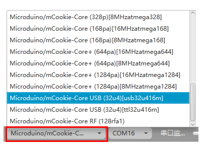
| − | * | + | *Step1: Select the right board card(Core USB 32U4) and COM port(Recognized automatically by default). |
[[File:mixly_board_COM.jpg|400px|center]] | [[File:mixly_board_COM.jpg|400px|center]] | ||
| − | * | + | *Step2: You can hear the buzzer after uploading successfully. Change the frequency of the buzzer '''Upload again''' to see what happens. |
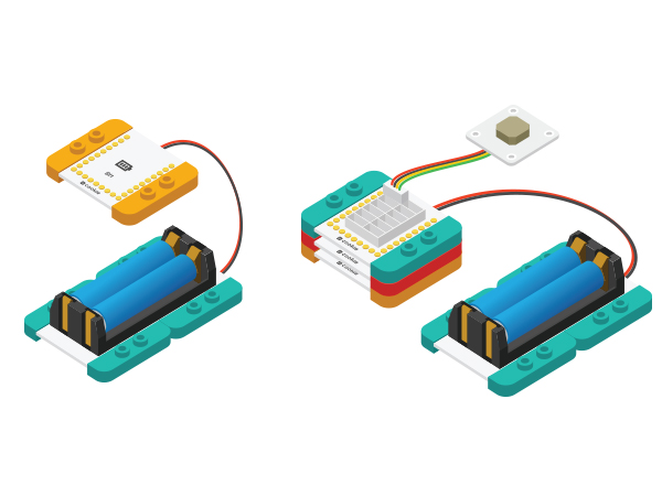
*The steps above are based on debugging on the computer. The code is inside the core module after uploading, which can also be powered by battery box. | *The steps above are based on debugging on the computer. The code is inside the core module after uploading, which can also be powered by battery box. | ||
[[File:MicroduinoBuzzer-Equipment-ok.jpg|600px|center]] | [[File:MicroduinoBuzzer-Equipment-ok.jpg|600px|center]] | ||
| Line 58: | Line 58: | ||
==Debugging== | ==Debugging== | ||
| − | * | + | *Step1: Select the right board card(Core USB 32U4) and COM port(Recognized automatically by default). |
[[File:mixly_board_COM.jpg|400px|center]] | [[File:mixly_board_COM.jpg|400px|center]] | ||
| − | * | + | *Step2: The buzzer will produce different sounds continuously after uploading successfully, achieving the effect of alarming. |
=Experiment 3: Compose Music with Buzzer= | =Experiment 3: Compose Music with Buzzer= | ||
| Line 86: | Line 86: | ||
==Debugging== | ==Debugging== | ||
| − | * | + | *Step1: Select the right board card(Core USB 32U4) and COM port(Recognized automatically by default). |
[[File:mixly_board_COM.jpg|400px|center]] | [[File:mixly_board_COM.jpg|400px|center]] | ||
| − | * | + | *Step2: You can hear the buzzer play birthday music after uploading. Users can change music based this principle. |
|} | |} | ||
Latest revision as of 09:45, 13 September 2016
ContentsFunction of the Module
Equipment
Experiment 1: Buzzer Makes a SoundOverallThe buzzer here we use is passive, which needs a certain frequency to drive. High voltage can't get it alarmed. Hardware BuildupSetup 1: Connect the interface on the back of the buzzer with the D6 port of the Hub. Setup 2: Connect the CoreUSB, Hub and Buzzer together to the computer with a USB cable. Mixly Programming
Debugging
Example 2: Buzzer Gives an AlarmOverviewTo make the buzzer give an alarm. Hardware BuildupSame with【Experiment 1: Buzzer Makes a Sound】. Mixly Programming
Debugging
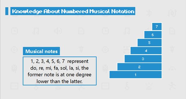
Experiment 3: Compose Music with BuzzerOverallTo use a buzzer instead of an audio speaker to play music and generate sound with different tones. Hardware BuildupSame with【Experiment 1: Buzzer Makes a Sound】. Mixly ProgrammingLet's firstly get to learn numbered music notation-Note.
Description for "Array"
Debugging
|


