|
|
| Line 19: |
Line 19: |
| | | | | | |
| | | | |
| − | ==Specifications== | + | ==Specification== |
| − | * Single chip USB to asynchronous serial data transfer interface.
| + | The USBTTL is an interface conversion chip, which can achieve the conversion from USB to the serial UART interface or to the synchronous/asynchronous Bit-Bang interface mode. FTDI provides driving programs under all kinds of operation systems. Microduino-USBTTL is arduino compatible with simple design, easy to use. |
| − | * Entire USB protocol handled on the chip - No USB-specific firmware programming required.
| + | * Integrate EEPROM, which can be used in IO configuration or saving USB VID serial number and production description information. |
| − | * UART interface support for 7 or 8 data bits, 1 or 2 stop bits and odd/even/mark/space/no parity.
| + | * Integrate electrical level converter, making its I/O level support 5V-2.8V voltage range. |
| − | * Fully assisted hardware or X-On/X-Off software handshaking.
| + | *With high driving ability of the I/O pin, it can drive multiple devices. |
| − | * Data transfer rates from 300 baud to 3 Megabaud (RS422/RS485 and at TTL levels) and 300 baud to 1 Megabaud (RS232).
| + | *With a power-on reset circuit and a supply decoupling RC circuit integrated inside, the chip can generate clock function automatically and needs no extra crystal oscillator, saving costs. |
| − | * Auto transmit buffer control for RS485 applications.
| + | * Conform to RoHS standard. |
| − | * Transmit and receive LED drive signals.
| + | |
| − | * New 48MHz, 24MHz,12MHz, and 6MHz clock output signal Options for driving external MCU or FPGA.
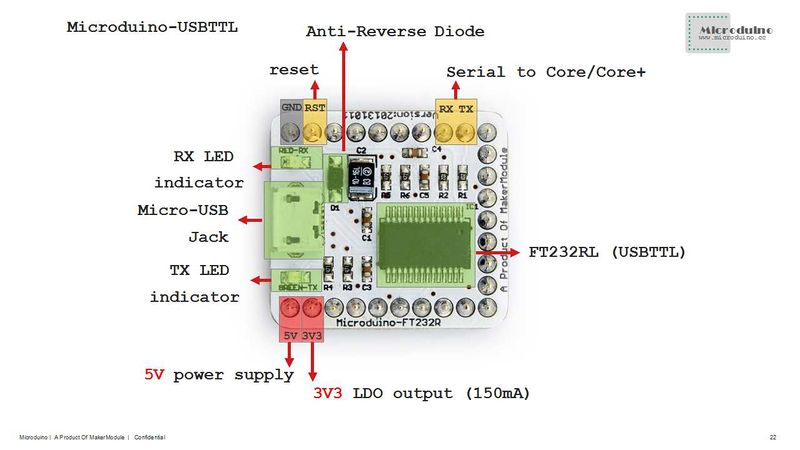
| + | :[[file:Micromodule-FT232R-PinoutBig1.jpg|800px|thumb|center|Microduino-FT232R-Pinout]] |
| − | * 256 Byte receive buffer and 128 Byte transmit buffer utilising buffer smoothing technology to allow for high data throughput.
| |
| − | * Synchronous and asynchronous bit bang mode interface options with RD# and WR# strobes. | |
| − | * Integrated 1024 bit internal EEPROM for I/O configuration and storing USB VID, PID, serial number and product description strings.
| |
| − | * Device supplied preprogrammed with unique USB serial number. | |
| − | * Support for USB suspend/resume.
| |
| − | * Support for bus powered, self powered, and high-power bus powered USB configurations.
| |
| − | * Integrated 3.3V level converter for USB I/O .
| |
| − | * Integrated level converter on UART and CBUS for interfacing to 5V - 1.8V Logic.
| |
| − | * True 5V/3.3V/2.8V/1.8V CMOS drive output and TTL input.
| |
| − | * High I/O pin output drive option. | |
| − | * Integrated USB resistors.
| |
| − | * Integrated power-on-reset circuit. | |
| − | * Fully integrated clock - no external crystal, oscillator, or resonator required.
| |
| − | * UART signal inversion option.
| |
| − | * USB bulk transfer mode.
| |
| − | * 3.3V to 5.25V Single Supply Operation. | |
| − | * UHCI/OHCI/EHCI host controller compatible.
| |
| − | * USB 2.0 Full Speed compatible.
| |
| | | | |
| − | :[[file:Micromodule-FT232R-Pinout.jpg|800px|thumb|center|Microduino-FT232R-Pinout]]
| |
| | | | |
| | |- | | |- |
|
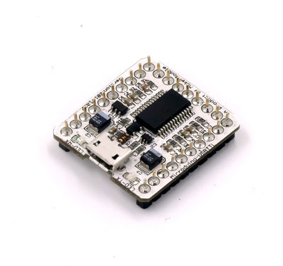
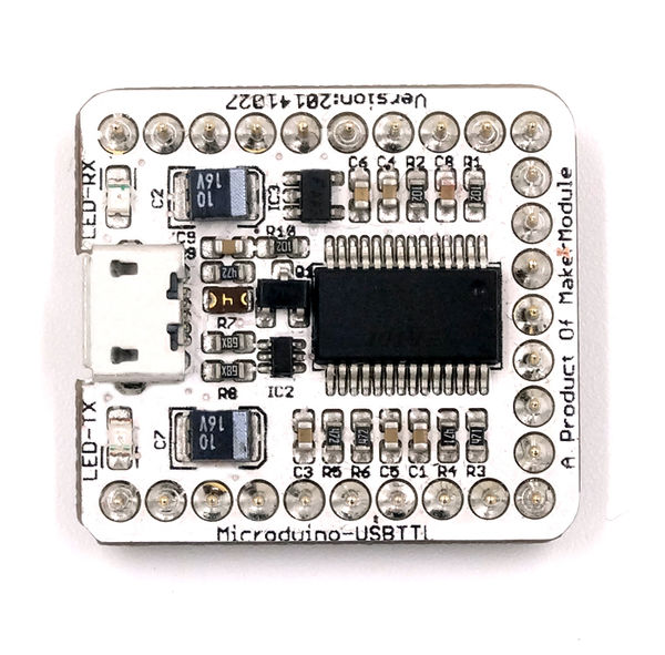
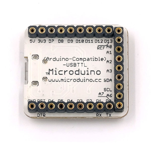
Microduino-USBTTL is based on FDTI FT232RL chip (Arduino embedded driver). It can be stacked with Microduino-Core or Microduino-Core+, enable Microduino core modules to communicate with PC.
|
Features
- Integrate EEPROM, which can be used for IO configuration as well as storage of VID USB sequence number and product description information (PID).
- Integrate the level converter, making its I/O port level to support the wide range of 5V - 2.8V;
- With strong I/O pin driver, it can drive multiple devices or longer data lines;
- With power-on reset circuit integrated, the chip can generate its own clock without the need for external crystal clock oscillator;
- Integrate power supply decoupling RC circuit for cost saving and confrom to RoHS standards
|
Specification
The USBTTL is an interface conversion chip, which can achieve the conversion from USB to the serial UART interface or to the synchronous/asynchronous Bit-Bang interface mode. FTDI provides driving programs under all kinds of operation systems. Microduino-USBTTL is arduino compatible with simple design, easy to use.
- Integrate EEPROM, which can be used in IO configuration or saving USB VID serial number and production description information.
- Integrate electrical level converter, making its I/O level support 5V-2.8V voltage range.
- With high driving ability of the I/O pin, it can drive multiple devices.
- With a power-on reset circuit and a supply decoupling RC circuit integrated inside, the chip can generate clock function automatically and needs no extra crystal oscillator, saving costs.
- Conform to RoHS standard.
|
Documents
|
Development
Download the driver: http://www.ftdichip.com/Drivers/VCP.htm
Uploading Arduino program to Microduino-Core/Core+ with Microduino-USBTTL
- 1. Install Arduino IDE: Microduino use the same IDE as Arduino, please download Arduino IDE from 【Arduino IDE official】 and install it in your disk. (if you already have it, just skip this step). Please check Arduino IDE details from 【Reference】 and 【Workshop】.
- 2. Patch Microduino package: Please download Microduino package for Arduino IDE from 【download】, and unzip is to {Your Arduino Install Driectory}/hardware directory.
- Microduino Arduino IDE Reference workshop: 【Arduino IDE Microduino Configuration】.
- 3. Programming: Upload program to Microduino-Core or Microduino-Core+ through Arduino IDE, with Microduino-USBTTL module.
- 4. Enjoy your Microduino journey!
|
Applications
The USB2TTL datasheet at http://www.ftdichip.com/Support/Documents/DataSheets/ICs/DS_FT232R.pdf says you can draw up to 50 mA from the FT232R 3.3V output.
|
FQA
- Can the external power work with Microduino-USBTTL for power supply?
- • Since the current of USBTTL is small (less than 100ma), we don't suggest using them together. You can only use USBTTL during the testing phase and are allowed to use the external power supply after finishing the program debugging.
- The PC can't identify the FT232 module which worked well previously.
|
Buy
|
History
- 2013/02/27: the second formal release.
- 2012/11/17: the first formal release, fix bugs in beta version.
- 2012/11/05: beta release, problem shooting:
- 5V power was not connect to Microduino interface
- Micro USB socket was not stable, it might be broken after several times plug.
|
Pictures
|


