Difference between revisions of "The Use of Buzzer"
(quotes) |
|||
| Line 29: | Line 29: | ||
==Experiment One: Let the Buzzer ring == | ==Experiment One: Let the Buzzer ring == | ||
===Build Module Circuit === | ===Build Module Circuit === | ||
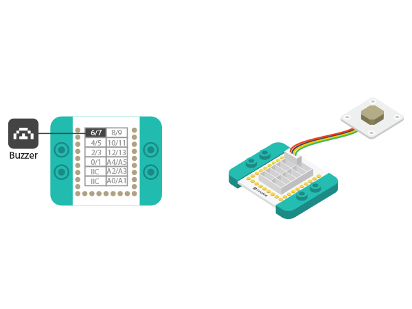
| − | *Setup | + | *Setup 1: Connect the Microduino-Sound sensor to the corresponding port(6) of the Hub with a sensor wire. |
[[File:MicroduinoBuzzer-D6.jpg|600px|center]] | [[File:MicroduinoBuzzer-D6.jpg|600px|center]] | ||
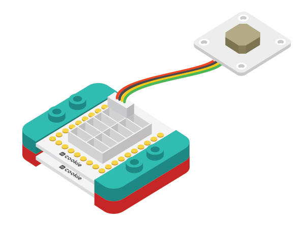
| − | *Setup | + | *Setup 2: Stack the Hub and CoreUSB together in any order. |
[[File:MicroduinoBuzzer-hub-coreusb.jpg|600px|center]] | [[File:MicroduinoBuzzer-hub-coreusb.jpg|600px|center]] | ||
===Debugging=== | ===Debugging=== | ||
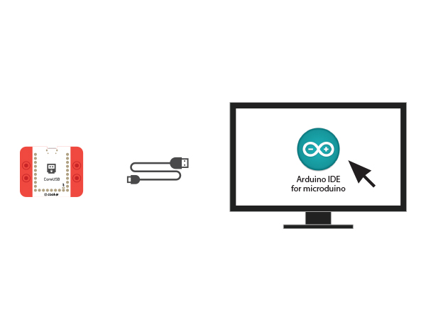
| − | *Setup | + | *Setup 1: Use a USB cable to connect the CoreUSB to your PC/MAC, then open Arduino IDE. |
[[File:CoreUSB_Ble_pc.jpg|600px|center]] | [[File:CoreUSB_Ble_pc.jpg|600px|center]] | ||
| − | * Setup | + | * Setup 2: Load the code and copy the program code into IDE. |
<source lang="cpp"> | <source lang="cpp"> | ||
#define buzzer_pin 6 //Define buzzer driving pin | #define buzzer_pin 6 //Define buzzer driving pin | ||
| Line 53: | Line 53: | ||
</source> | </source> | ||
Select Microduino-CoreUSB as the board and COMXX as the port; Click the right arrow(—>) to upload the program. After you see "Done Uploading", it means the program has been written into the CoreUSB module. And after that is done, you can hear the buzzer ring. | Select Microduino-CoreUSB as the board and COMXX as the port; Click the right arrow(—>) to upload the program. After you see "Done Uploading", it means the program has been written into the CoreUSB module. And after that is done, you can hear the buzzer ring. | ||
| − | * | + | *"tone(pin,fre)" function |
**The specified pin and output frequency's signals. | **The specified pin and output frequency's signals. | ||
**Users can change the value of buzzer_fre to watch buzzer changes. | **Users can change the value of buzzer_fre to watch buzzer changes. | ||
| Line 81: | Line 81: | ||
} | } | ||
</source> | </source> | ||
| − | + | "for(int i=200;i<=800;i++)" - Description: The value of "i" starts at 200, then increases by 1 each time the "for" loop reiterates while the "i" value is less than or equal to 800. Users can change these max and min values of "i" to adjust the sounds the buzzer cycles through. | |
==Experiment Three: Play songs == | ==Experiment Three: Play songs == | ||
Latest revision as of 06:37, 30 September 2016
| Language: | English • 中文 |
|---|
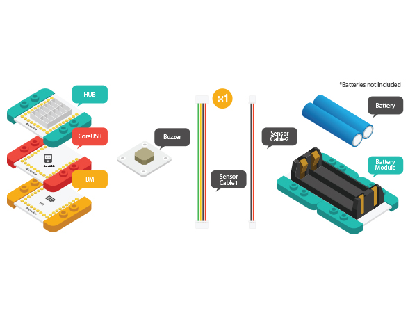
ContentsObjectiveThis tutorial will introduce you the use of Microduino-Buzzer through three experiments. Equipment
IntroductionGenerally, buzzer can be classified as active buzzer and passive buzzer. Microduino-Buzzer adopts passive buzzer.
Experiment One: Let the Buzzer ringBuild Module Circuit
Debugging
#define buzzer_pin 6 //Define buzzer driving pin
#define buzzer_fre 600 //Define buzzer output frequency

void setup()
{
  pinMode(buzzer_pin,OUTPUT);
}

void loop()
{
    tone(buzzer_pin,buzzer_fre);    //Drive the buzzer
}
Select Microduino-CoreUSB as the board and COMXX as the port; Click the right arrow(—>) to upload the program. After you see "Done Uploading", it means the program has been written into the CoreUSB module. And after that is done, you can hear the buzzer ring.
Experiment Two: Buzzer Makes Alarm
#define buzzer_pin 6 //Define buzzer driving pin

void setup()
{
  pinMode(buzzer_pin,OUTPUT);
}

void loop()
{
  for(int i=200;i<=800;i++) { //Increase the frequency from 200HZ to 800HZ in a circular manner.
    tone(buzzer_pin,i);    //Output frequency in N0.6 port.
    delay(5);      //The frequency lasts for 5ms.
  }
  delay(2000);     //The highest frequency lasts for 2s.
  for(int i=800;i>=200;i--)
  {
    tone(buzzer_pin,i);
    delay(10); //The frequency lasts for 10ms.
  }
}
"for(int i=200;i<=800;i++)" - Description: The value of "i" starts at 200, then increases by 1 each time the "for" loop reiterates while the "i" value is less than or equal to 800. Users can change these max and min values of "i" to adjust the sounds the buzzer cycles through. Experiment Three: Play songs
#define buzzer_pin 6 //Define buzzer driving pin
int song[] = {
  262, 262, 294, 262, 349, 330,
  262, 262, 294, 262, 392, 349,
  262, 262, 523, 440, 349, 330, 294,
  466, 466, 440, 349, 392, 349
};

int noteDurations[] = {
  4, 4, 2, 2, 2, 1,
  4, 4, 2, 2, 2, 1,
  4, 4, 2, 2, 2, 2, 1,
  4, 4, 2, 2, 2, 1
};

void setup() {
  pinMode(buzzer_pin, OUTPUT);
}

void loop() {
  song_play();
}

void song_play()
{
  for (int thisNote = 0; thisNote < 25; thisNote++)
  {
    int noteDuration = 1000 / noteDurations[thisNote];
    tone(buzzer_pin, song[thisNote], noteDuration);
    int pauseBetweenNotes = noteDuration * 1.20;
    delay(pauseBetweenNotes);
    noTone(buzzer_pin);
  }
}
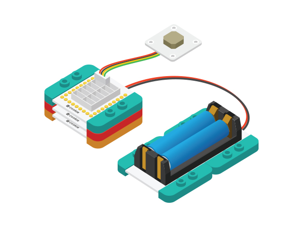
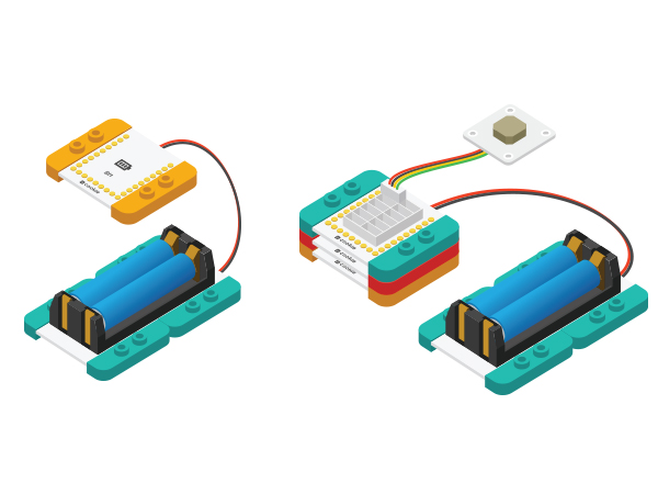
Connect the activated battery box to the BM module, and then stack all the modules together in any order. Congratulations! You've finished the circuit buildup. |
