Difference between revisions of "Sensor-IO Split"
From Microduino Wiki
(→Introduction of Pins) |
(→Introduction of Pins) |
||
| Line 26: | Line 26: | ||
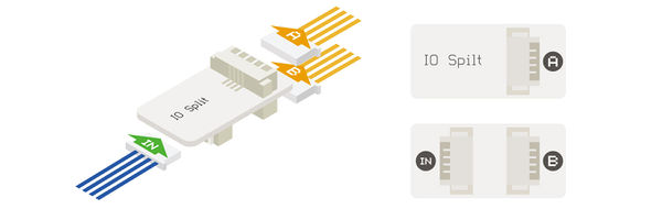
After connect the '''IN interface''' to one interface of Sensor Hub, the extended “A port” is corresponding to the “even pins” of Sensor Hub, and the “B interface” is corresponding to the “odd pins” of Sensor Hub. | After connect the '''IN interface''' to one interface of Sensor Hub, the extended “A port” is corresponding to the “even pins” of Sensor Hub, and the “B interface” is corresponding to the “odd pins” of Sensor Hub. | ||
| − | For example, connecting to the 6/7 pin of Hub, the corresponding pin of A is 6 | + | For example, connecting to the 6/7 pin of Hub, the corresponding pin of A is 6, and the corresponding pin of B is 7. |
==Document== | ==Document== | ||
Revision as of 23:22, 12 April 2017
| Language: | English • 中文 |
|---|
|
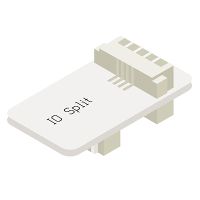
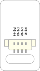
Sensor-IO-split can split a 4PIN interface into 2. This gives access to the second GPIO on the standard sensor / trinket header. Introduction of Pins
After connect the IN interface to one interface of Sensor Hub, the extended “A port” is corresponding to the “even pins” of Sensor Hub, and the “B interface” is corresponding to the “odd pins” of Sensor Hub. For example, connecting to the 6/7 pin of Hub, the corresponding pin of A is 6, and the corresponding pin of B is 7. Document
ApplicationIt can be used to divide the two IO signals of one 4PIN port in Sensor Hub into two 4PIN ports.
PurchaseGallery
|


