Difference between revisions of "Cube Robot"
(→Joypad Buildup & Debugging) |
|||
| Line 68: | Line 68: | ||
==Document== | ==Document== | ||
| − | |||
| − | |||
| − | |||
*Github Download | *Github Download | ||
Revision as of 07:17, 6 July 2016
ContentsOutline
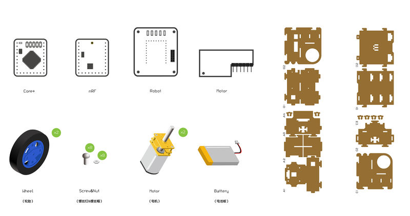
Bill of Materials
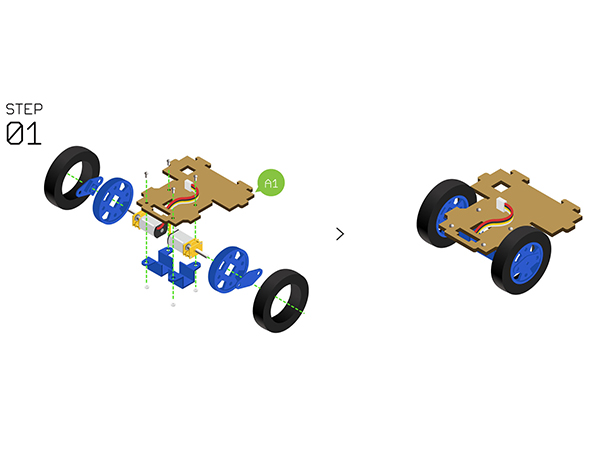
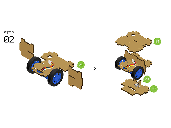
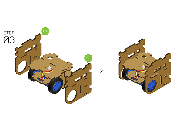
PrincipleThere are many robot cars such as tracking, obstacle and Bluetooth remote controlling car or computer mouse, which shares the same control mode, namely, moving in four directions. Off course, they are different in structure and function. Here we're talking about two-wheel-driving mode. By controlling the rotation direction of two wheels, it can realize moving forward or backward, spinning and other functions, which combines with a universal wheel to keep balance. This Cube Robot car has a simple structure, including wheels, body frame and control system. 1)The wheels adopt two reducer motors with large torque and PWN speed adjustment, making them easy to control. 2)The body structure adopts wooden board with a size of 8cm*8cm*8cm. 3)The whose control system contains four parts:
Since the Cube Robot car is small, here we adopt the lithium battery.
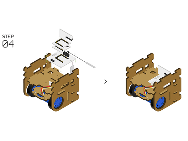
The CPU of the car adopts Microduino-Core.
The car adopts Microduino-nRF24 wireless communication, which owns quick response and about 100m control range in the open area.
It adopts Microduino-Robot DC motor driving motor--a module that can drive two motor and can connect the CPU and the DC motor modules together. Document
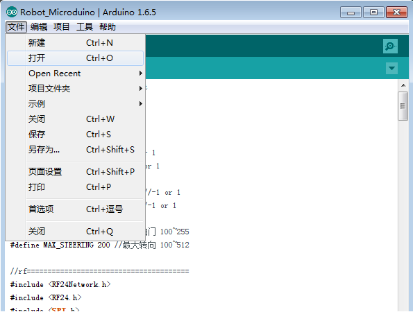
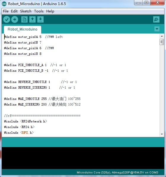
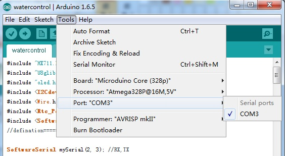
DebuggingPlease stack the Microduino-Core and Microduino-USBTTL together, and upload the program from the Microduino-USBTTL to Microduino-Core with a USB cable. Note: Please upload the program before stacking all modules together. Open the Arduino IDE.(If you don't have the IDE, you can refer to the appendix to install it by click【Files】→【Open】.) Browse to the program address, click " Robot_Microduino.ino " and open. Click "√" on the top and compile, click Tools, select the Micrdouino-Core (Atmega328P@16M,5V) and the COMX as the port, click "→" and download the program to the developing board. Cube Robot Installation
Joypad Buildup
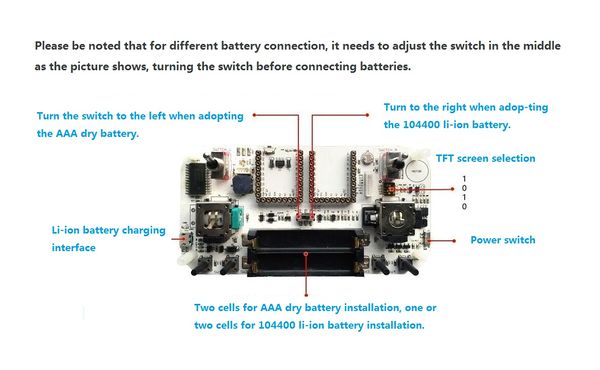
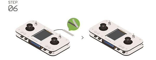
Note: For different battery connection, please dial the switch in the middle as the picture shows. You need to adjust the switch firstly and then connect batteries.
Joypad Buildup & Debugging
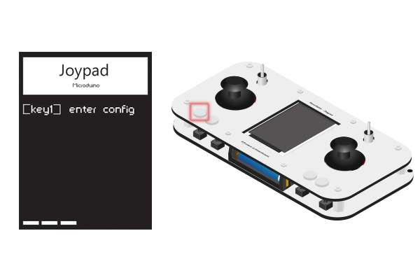
Press Key1 in 4s after opening the Joypad , it'll enter the Config mode.
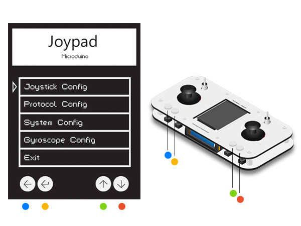
Key 1- Key 4 from the left to right as the picture shows below. Note: You have to enter the setting mode before the OS interface. (4s) If not, please restart.
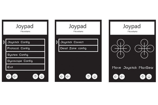
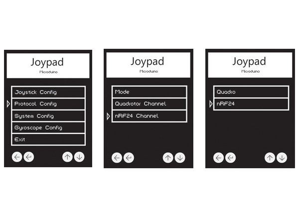
Press Key3 and Key4 to move the cursor. Be noted of the Key1 points to "Return" and the Key2 refers to "Confirm". Select Joystick Config to enter the setting mode. And choose Joystick Correct to enter the calibration mode. After that, it'll appear the interface shown in the third picture with an initializing state of two crosses. At the this time, you can move the joystick around. Then, you can see circles in four directions and biggest circle means the Joystick has been turned to the limit position. Press Key2 to confirm after the calibration and return to the last page.
Press Key1 to return to the main page and select Protocol Config to enter mode selection. Select the first Mode, then choose nRF24(namely, Robot control mode), press Key2 to confirm and return.
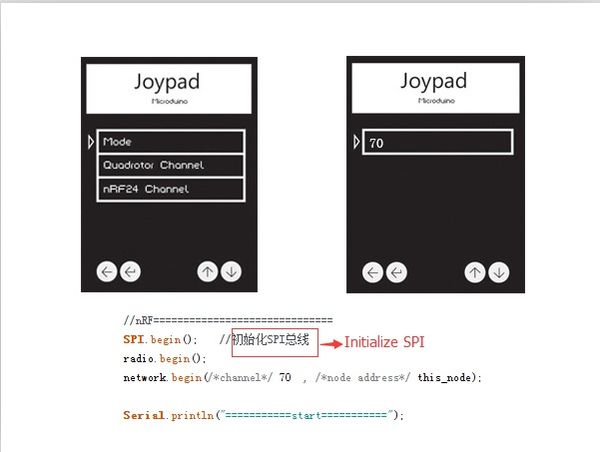
Return to the secondary list, select nRF24 Channel and press Key2 to confirm. Select 70, which corresponds to the function setting of the nRF24 in Robot_Microduino.ino. By this step, you have completed the Microduino Cube Robot car and the Joypad installation. Attention
Program Description
In def.h, it defines: uint8_t nrf_channal = 70; //0~125nrf_channal is the NRF communication channel, which is included in the code of both the Joypad and the Cube Robot car. When the channel is consistent, the Joypad and the Cube Robot car will be connected successfully. In the car code, it'll show program sections as follows: //nRF==============================
SPI.begin(); //Initialize SPI
radio.begin();
network.begin(/*channel*/ 70 , /*node address*/ this_node);在data.h中 outBuf[0] = Joy1_x;
outBuf[1] = Joy1_y;
outBuf[2] = Joy_x;
outBuf[3] = Joy_y;
outBuf[4] = map(AUX[0], 0, 1, Joy_MID - Joy_maximum, Joy_MID + Joy_maximum);
outBuf[5] = map(AUX[1], 0, 1, Joy_MID - Joy_maximum, Joy_MID + Joy_maximum);
outBuf[6] = map(AUX[2], 0, 1, Joy_MID - Joy_maximum, Joy_MID + Joy_maximum);
outBuf[7] = map(AUX[3], 0, 1, Joy_MID - Joy_maximum, Joy_MID + Joy_maximum);The 8-bit array "outBuf" represents 8 data sent from the Joypad. 0: left and right control of the right rod. 1: up and down control of the right rod. 2: left and right control of the left rod. 3: up and down control of the left rod. Bit 4~7 correspondS to AUX0~4. In nrf.h struct send_a //Send
{
uint32_t ms;
uint16_t rf_CH0;
uint16_t rf_CH1;
uint16_t rf_CH2;
uint16_t rf_CH3;
uint16_t rf_CH4;
uint16_t rf_CH5;
uint16_t rf_CH6;
uint16_t rf_CH7;
};Here "send_a" correponds to the data sent from the 0 bit.
Below is the definition about controlling the left and right wheel movement of the reducer motor. #define motor_pin0A 5 //PWM left
#define motor_pin0B 7
#define motor_pin1A 6 //PWM
#define motor_pin1B 8Here "receive_a" corresponds to "send_a" in the Joypad program. struct receive_a //Receive
{
uint32_t ms;
uint16_t rf_CH0;
uint16_t rf_CH1;
uint16_t rf_CH2;
uint16_t rf_CH3;
uint16_t rf_CH4;
uint16_t rf_CH5;
uint16_t rf_CH6;
uint16_t rf_CH7;
};Select CH3 as the left rod to control the Cube Robot fore and aft, and the CH0 as the right rod to control left and right. _i[0] = map(rec.rf_CH3, 1000, 2000, -MAX_THROTTLE, MAX_THROTTLE);
_i = _turn;
_i[0] = map(rec.rf_CH0, 1000, 2000, -MAX_STEERING, MAX_STEERING);Video |
