Difference between revisions of "Open Source LED Dot Matrix Clock"
(→Installation) |
(→Installation) |
||
| Line 90: | Line 90: | ||
|width="50%" valign="top" align="left"| | |width="50%" valign="top" align="left"| | ||
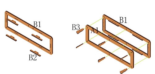
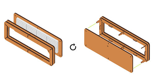
*'''Step1''': | *'''Step1''': | ||
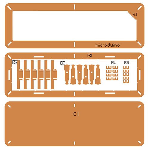
| − | **Insert | + | **Insert '''structure B2''' vertically into '''structure B1'''. |
| − | **Use ''' structure B3''' to connect '''structure A1''' and '''structure B1'''. | + | **Use '''structure B3''' to connect '''structure A1''' and '''structure B1'''. |
|width="50%" valign="top" align="left"| | |width="50%" valign="top" align="left"| | ||
[[File:DotMatrixjiegou1.jpg|500px|center|thumb]] | [[File:DotMatrixjiegou1.jpg|500px|center|thumb]] | ||
|} | |} | ||
| − | |||
{| border="0" cellpadding="10" width="100%" | {| border="0" cellpadding="10" width="100%" | ||
| Line 101: | Line 100: | ||
|width="50%" valign="top" align="left"| | |width="50%" valign="top" align="left"| | ||
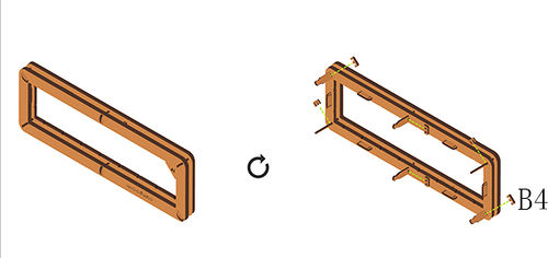
*'''Step2''': | *'''Step2''': | ||
| − | **Use '''structure | + | **Use '''structure B4'''to jam the '''structure A1''' and '''structure B1''' . |
|width="50%" valign="top" align="left"| | |width="50%" valign="top" align="left"| | ||
| − | [[File: | + | [[File:DotMatrixjiegou3.jpg|500px|center|thumb]] |
|} | |} | ||
| Line 111: | Line 110: | ||
|width="50%" valign="top" align="left"| | |width="50%" valign="top" align="left"| | ||
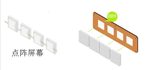
*'''Step3''': | *'''Step3''': | ||
| − | ** | + | **To change the IIC address of the dot matrix module, you can refer to '''[[https://www.microduino.cn/wiki/index.php/Microduino-Module_Dot_Matrix#.E7.82.B9.E9.98.B5.E5.9C.B0.E5.9D.80.E8.AE.BE.E7.BD.AE.E6.96.B9.E6.B3.95 The method of setting the IIC address of the dot matrix module ]]''' tutorial. |
| + | **Connect the dot matrix modules of which the IIC address have been changed in order that from left to right according to to defined address, to complete the cascade. | ||
| + | **Stick piece of four double sides adhesive tape on the back of '''structure C1''' equidistantly, and stick '''[[Microduino-Dot Matrix]]''' to '''structure C1'''('''put the side with letters of the dot matrix down''')successively. | ||
| + | **As the following figure, reserve the cable of the '''key end interface''' of the module in order to connect the '''IIC interface''' of '''[[Microduino-Cube-S1]]'''. | ||
|width="50%" valign="top" align="left"| | |width="50%" valign="top" align="left"| | ||
| − | [[File: | + | [[File:DotMatrix1jilian.jpg|500px|center|thumb]] |
|} | |} | ||
| Line 121: | Line 123: | ||
|width="50%" valign="top" align="left"| | |width="50%" valign="top" align="left"| | ||
*'''Step4''': | *'''Step4''': | ||
| − | ** | + | **Use '''structure B3''' to connect '''structure C1''' and '''structure A1,B1'''. |
| − | |||
| − | |||
|width="50%" valign="top" align="left"| | |width="50%" valign="top" align="left"| | ||
| − | [[File: | + | [[File:DotMatrixjiegou4.jpg|500px|center|thumb]] |
|} | |} | ||
| Line 133: | Line 133: | ||
|width="50%" valign="top" align="left"| | |width="50%" valign="top" align="left"| | ||
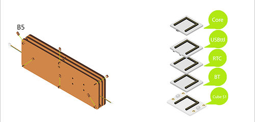
*'''Step5''': | *'''Step5''': | ||
| − | **Use | + | **Use '''structure B5''' to jam '''structure B3'''. |
| + | **Stack the following modules on the '''[[Microduino-Cube-S1]]'''. | ||
| + | ***'''[[Microduino-Core]]''' | ||
| + | ***'''[[Microduino-USBTTL]]''' | ||
| + | ***'''[[Microduino-RTC]]''' | ||
| + | ***'''[[Microduino-BT]]''' | ||
|width="50%" valign="top" align="left"| | |width="50%" valign="top" align="left"| | ||
| − | [[File: | + | [[File:DotMatrixjiegou7.jpg|500px|center|thumb]] |
|} | |} | ||
| − | |||
{| border="0" cellpadding="10" width="100%" | {| border="0" cellpadding="10" width="100%" | ||
| Line 143: | Line 147: | ||
|width="50%" valign="top" align="left"| | |width="50%" valign="top" align="left"| | ||
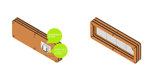
*'''Step6''': | *'''Step6''': | ||
| − | + | **Connect the module '''[[Microduino-Dot Matrix]]''' to the '''IIC interface''' of '''[[Microduino-Cube-S1]]'''. | |
| − | + | **Use '''nylon screws''' to fix '''[[Microduino-Cube-S1]]''' on the back of '''structure C1'''. | |
| − | |||
| − | |||
| − | |||
| − | **Connect the '''[[Microduino-Dot Matrix]]''' | ||
| − | **Use | ||
|width="50%" valign="top" align="left"| | |width="50%" valign="top" align="left"| | ||
Revision as of 07:46, 17 June 2016
| Language: | English • 中文 |
|---|
ContentsOutline
Bill of Materials
Principle of the Experiment
Program Download
Programming
**Note:Please upload programs before stacking all modules together.
Installation
Operating Instruction
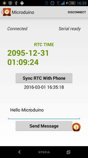
Bluetooth Connection
Display Text
Code InstructionCode to loading:File:Dot Maxtrix Clock.zip Dot Matrix Cascade uint8_t Addr[MatrixPix_X][MatrixPix_Y] = {
{ 64, 63, 62, 61}};
Define the IIC addresses of the four Dot Matrix modules as 64, 63, 62, and 61, and the arrangement type is 1x4. Bluetooth while (mySerial.available()) {...}
It is effective when there is a serial port data. mySerial.read() Red the data which is transferred by the UART. if (c == 't' && buffer_num == 0 && !buffer_sta_d)
buffer_sta_t = true;
if (c == 'm' && buffer_num == 0 && !buffer_sta_t)
buffer_sta_d = true;
Judge it is date or time data. strstr((char *)buffer, "t") Return the address where the "t" character first appears in buffer. sscanf((char *)strstr((char *)buffer, "t"), "t%d,%d,%d,%d,%d,%d", &sta[0], &sta[1], &sta[2], &sta[3], &sta[4], &sta[5]); From the address where the "t" character first appears in buffer, read the value according to the %d type, and write into sta[]. bleUpdata() Transfer data through UART, only by clicking the button on your mobile phone to send the specified character. If loosing, it will send character“0”. So without press, it will always show time. RTCrtc.getDate(); rtc.getTime(); setTime(rtc.getHour(), rtc.getMinute(), rtc.getSecond(), rtc.getDay(), rtc.getMonth(), rtc.getYear()) Get the date and time data of rtc. rtc.setDate(day(), weekday() , month(), 0, year() - 2000); //day, weekday, month, century(1=1900, 0=2000), year(0-99) rtc.setTime(hour(), minute() , second()); //hr, min, sec Set by hour, minute, second, day, month, and year format. Displaydisplay.print(second() % 2 ? " " : ":"); The second flashes, after being used justify whether the second can be exactly divided by 2. If it can, show it. If not, don’t show. display.getDeviceAddr(a) Get the IIC address of the device. display.getWidth(),display.getHeight() Return the X,Y coordinates. display.setLedColor(x, y, random(0, 255), random(0, 255), random(0, 255)) Set the color of each LED randomly. display.clearDisplay() Clean up the screen. display.setColor(X,Y,Z) Set the color of the full screen X:Red Y:Green Z:Blue display.writeString("string", MODE, time ,z)
string:any string. MODE:MODE_H displays characters horizontally. /MODE_V displays characters vertically. time:The displayed time(the flow velocity of the characters on the screen). z:X/Y coordinate. Through reading the RTC color, display the specific values in the form of coordinates. FAQ
|

