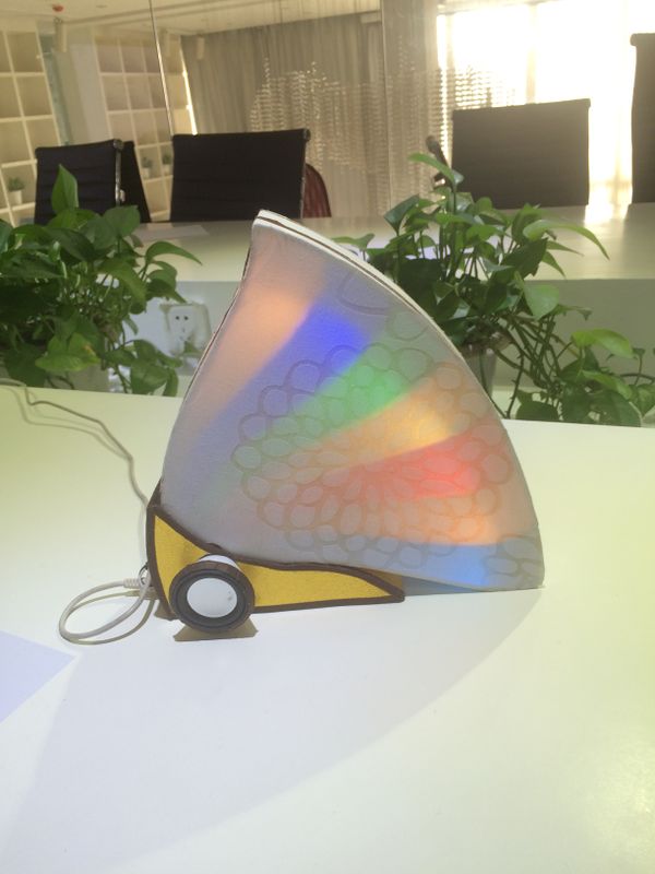
Microduino Butterfly Light

From Microduino Wiki
Revision as of 07:01, 6 February 2015 by 1304410487@qq.com (talk) (Program Download)
Jump to: navigation, search

Outline

  • Project: Butterfly light
  • Purpose: Butterfly light is a touch control color-changing music light.
  • Difficulty: Middle-level
  • Time-consuming: 6-Hour
  • Maker: Guysgogo&&Microduino

Team Introduction

Setup gusgogo logo.jpg


Guysgogo is team composed of four senior students in the maker class of LKK Intelligent Hardware Industrial Design. Three of the students—Run Jiang, Huiyu Hao, Tingyu Li and Chaohui Xie, are college students from Hebei.

Bill of Material

  • Microduino Equipment
Module Number Function
Microduino-Core+ 1 Core board
Microduino-USBTTL 1 Program download
Microduino-Audio 1 Audio control
Microduino-Amplifier 1 Amplifier module
Microduino-Sensorhub 1 Sensor connection board
Microduino-Cube-S1 1 Base board
Microduino-Lantern 7 Colorful LED light
Microduino-Touch 7 Touch sensor
  • Other Equipment
Equipment Number Function
Loudspeaker 1
MicroUSB cable 1 Power supply

Document

Program download: Butterfly_light

3D model download: File:3D-Butterfly light.zip

Build 3D Model

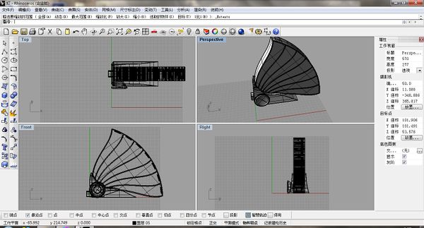
The model adopts buttery shape.

3dm light1.jpg

Build Hardware Circuit

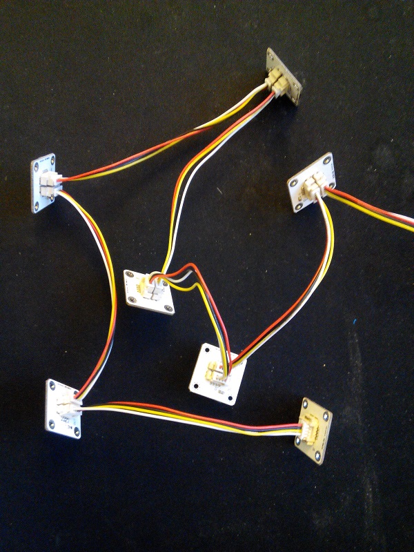
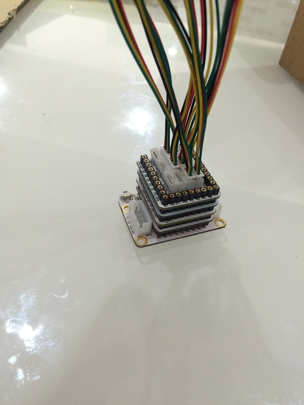
  • The colorful LED light adopts built-in IC control chip. With one-wire bus control, you only need one I/O port to control. Just connect the OUT interface of one Lantern to the IN interface of the other Lantern, and then join up the IN interface to Microduino core board via Sensorhub.
Light steup.jpg
  • Each touch sensor needs a Microduino I/O port to drive. We can tell if it is pressed by reading sensor values via digital port and analog port.
Touch steup.jpg
  • You can debug software after building the hardware circuit.

Prepare Audio

  • Download audio file:File:Music-Butterfly light.zip
  • Connect Microduino-Audio module with your computer via USB cable. It will show a disk named “microduino” after successful connection. Just open the disk and select audio file, then write to flash.

Software Debugging

Program Description

  • “audio.h”file is used for music play control and “key.h” file is for touch detection.
    • Audio module is connected to Serial 1 to control by default.
    • As for touch sensor pin definition, users can change according to personal needs:
  int sensor_pin[7]=
{
  4,8,10,12,A0,A2,A6
};
    • The colored LED light defines seven lights, whose light control pin is D6:
#define PIN 6
Adafruit_NeoPixel strip = Adafruit_NeoPixel(7, PIN, NEO_GRB + NEO_KHZ800);
  • How to judge the touch of seven lights & how to control music and LED lights:
    • When pressing some a button, it will play music and the white led light will blink.
    • When pressing twice one time, the white led will go on.
    • When pressing three times once, you can change the light color.
    • Anytime, one press means turning off the light.
  for(int a=0;a<7;a++)
  {
    {
      if(key_get(sensor_pin[a],1))		//When triggered,  
      {
        //colorWipe(strip.Color(255, 255, 0), 10);
        sensor_vol_cache[a]++;	//Counting
        // Serial.print("+");
        if(sensor_vol_cache[a]>3)
          sensor_vol_cache[a]=3;

        {
          colorWipe(color[8], a);

          num=a;

          audio_choose(a+1);
          audio_play();

          colorWipe(color[0], a);
        }

        time1[a]=millis();
      }

      if(millis()-time1[a]>500 && sensor_vol_cache[a]!=0)	//Just start it and delay for one second or more, and the scan is ended. 
      {
        if(sensor_vol_cache[a]==1)
        {
          colorWipe(color[0], a);
          Serial.println("LED_OFF");
        }
        else if(sensor_vol_cache[a]==2)
        {
          colorWipe(color[8], a);
        }
        else
        {
          randomSeed(millis()%1000);
          sensor_vol[a]=random(1,7);
          Serial.println("");
          Serial.print("num:");
          Serial.print(a);
          Serial.print(":");
          Serial.print(sensor_vol[a]);

          colorWipe(color[sensor_vol[a]], a);
        }
        sensor_vol_cache[a]=0;		//Return to zero and wait for the next scan.
      }
    }
  }

Program Download

  • Make sure you build Microduino IDE, or you can refer to:Microduino Getting start.
  • Make there is _99_LCD_NeoPixel library in IDE.
  • Open the downloaded program and select the right board to download after compiling.
  • After the download, you can test whether the function mentioned above is right or not by the Touch sensor. Meantime, you need to notice which LED light the Touch sensor corresponds to.

Overall Assembling

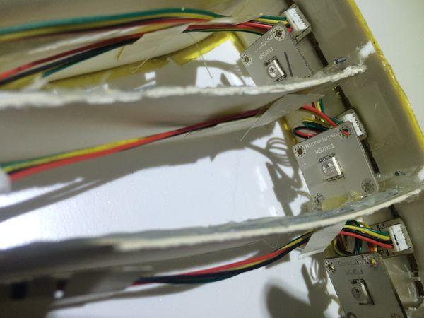
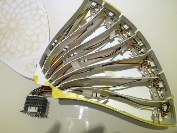
  • Fixate the light and the touch sensor on the outside of the 3D battery.
Setup 3d light1.jpg
Setup 3d light2.jpg
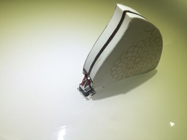
  • Wrap the battery with a beautiful exterior.
Setup 3d page.jpg
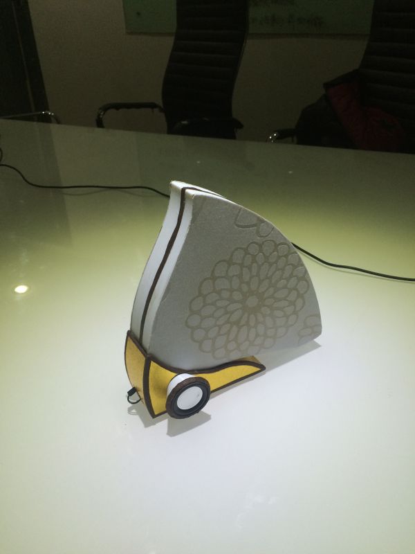
  • Fixate the loudspeaker on the base and then get it fixated with the battery.
Setup 3d buzzer.jpg
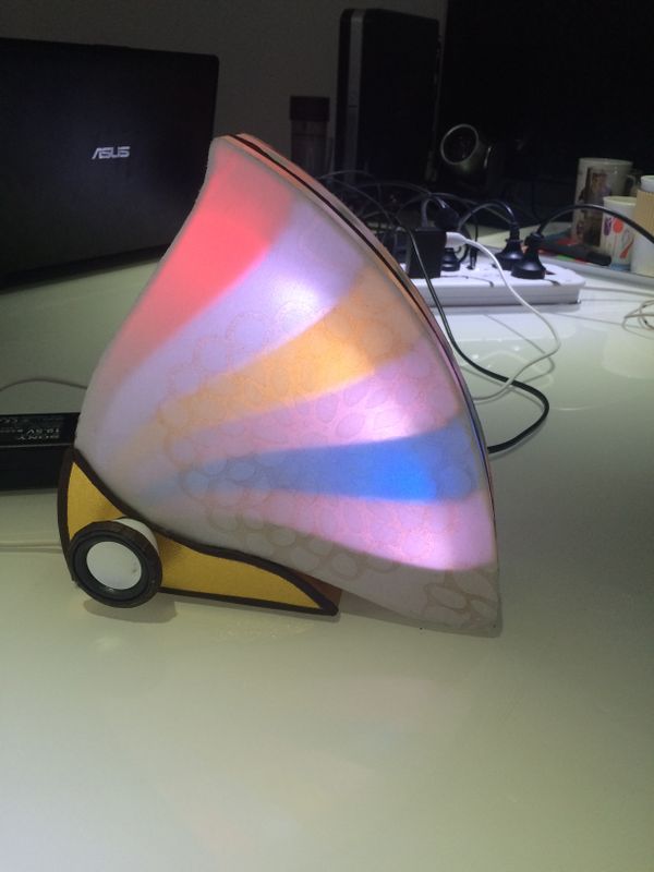
  • Plug in USB cable for power supply at last and have fun!
Setup 3d ok1.jpg
Setup 3d ok2.jpg

Notice

  • Since Audio adopts Serial 1 by default, please initialize Serial 1: “AUDIO_PORT.begin(9600);”
  • Please make sure the touch sensor corresponding with the lights.

Video

http://v.youku.com/v_show/id_XODc2NDMzODg4.html