Color Sensor
Contents[hide]OutlineMicroduino-Color detector is a color detection senor. This module adopts TCS3414CS color chip and it can be connected through IIC interface. Based on 8×2 filtered photodiode and 16-bit analog-digital converter, you can measure light or light reflection on the surface of an object to acquire color value. Specification
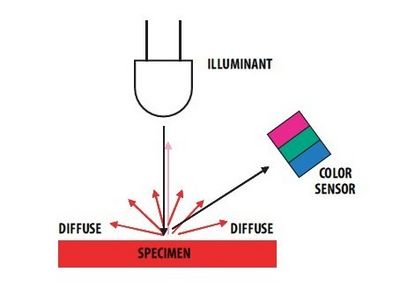
UsageWhen using, if it is to detect the color of light, then the sensor on the LED needs to close, and aims the light directly to the sensor. If it is to detect the color of objects, you need to open the sensor on the LED and aims it to the object. DevelopmentDevice
Preparation
Debugging
#include <Wire.h>
#include <math.h>
#define COLOR_SENSOR_ADDR  0x39//the I2C address for the color sensor
#define REG_CTL 0x80
#define REG_TIMING 0x81
#define REG_INT 0x82
#define REG_INT_SOURCE 0x83
#define REG_ID 0x84
#define REG_GAIN 0x87
#define REG_LOW_THRESH_LOW_BYTE 0x88
#define REG_LOW_THRESH_HIGH_BYTE 0x89
#define REG_HIGH_THRESH_LOW_BYTE 0x8A
#define REG_HIGH_THRESH_HIGH_BYTE 0x8B
#define REG_BLOCK_READ 0xCF
#define REG_GREEN_LOW 0xD0
#define REG_GREEN_HIGH 0xD1
#define REG_RED_LOW 0xD2
#define REG_RED_HIGH 0xD3
#define REG_BLUE_LOW 0xD4
#define REG_BLUE_HIGH 0xD5
#define REG_CLEAR_LOW 0xD6
#define REG_CLEAR_HIGH 0xD7
#define CTL_DAT_INIITIATE 0x03
#define CLR_INT 0xE0
//Timing Register
#define SYNC_EDGE 0x40
#define INTEG_MODE_FREE 0x00
#define INTEG_MODE_MANUAL 0x10
#define INTEG_MODE_SYN_SINGLE 0x20
#define INTEG_MODE_SYN_MULTI 0x30

#define INTEG_PARAM_PULSE_COUNT1 0x00
#define INTEG_PARAM_PULSE_COUNT2 0x01
#define INTEG_PARAM_PULSE_COUNT4 0x02
#define INTEG_PARAM_PULSE_COUNT8 0x03
//Interrupt Control Register
#define INTR_STOP 40
#define INTR_DISABLE 0x00
#define INTR_LEVEL 0x10
#define INTR_PERSIST_EVERY 0x00
#define INTR_PERSIST_SINGLE 0x01
//Interrupt Souce Register
#define INT_SOURCE_GREEN 0x00
#define INT_SOURCE_RED 0x01
#define INT_SOURCE_BLUE 0x10
#define INT_SOURCE_CLEAR 0x03
//Gain Register
#define GAIN_1 0x00
#define GAIN_4 0x10
#define GAIN_16 0x20
#define GANI_64 0x30
#define PRESCALER_1 0x00
#define PRESCALER_2 0x01
#define PRESCALER_4 0x02
#define PRESCALER_8 0x03
#define PRESCALER_16 0x04
#define PRESCALER_32 0x05
#define PRESCALER_64 0x06

int readingdata[20];
int i,green,red,blue,clr,ctl;
double X,Y,Z,x,y,z;
void setup()
{
	Serial.begin(9600);
	Wire.begin(); // join i2c bus (address optional for master)
}
void loop()
{
  setTimingReg(INTEG_MODE_FREE);//Set trigger mode.Including free mode,manually mode,single synchronizition mode or so.
  setInterruptSourceReg(INT_SOURCE_GREEN); //Set interrupt source
  setInterruptControlReg(INTR_LEVEL|INTR_PERSIST_EVERY);//Set interrupt mode
  setGain(GAIN_1|PRESCALER_4);//Set gain value and prescaler value
  setEnableADC();//Start ADC of the color sensor
  while(1)
 {
   readRGB();
   calculateCoordinate();
   delay(1000);
   clearInterrupt();
 }
}
/************************************/
void setTimingReg(int x)
{
   Wire.beginTransmission(COLOR_SENSOR_ADDR);
   Wire.write(REG_TIMING);
   Wire.write(x);
   Wire.endTransmission();
   delay(100);
}
void setInterruptSourceReg(int x)
{
   Wire.beginTransmission(COLOR_SENSOR_ADDR);
   Wire.write(REG_INT_SOURCE);
   Wire.write(x);
   Wire.endTransmission();
   delay(100);
}
void setInterruptControlReg(int x)
{
   Wire.beginTransmission(COLOR_SENSOR_ADDR);
   Wire.write(REG_INT);
   Wire.write(x);
   Wire.endTransmission();
   delay(100);
}
void setGain(int x)
{
   Wire.beginTransmission(COLOR_SENSOR_ADDR);
   Wire.write(REG_GAIN);
   Wire.write(x);
   Wire.endTransmission();
}
void setEnableADC()
{

   Wire.beginTransmission(COLOR_SENSOR_ADDR);
   Wire.write(REG_CTL);
   Wire.write(CTL_DAT_INIITIATE);
   Wire.endTransmission();
   delay(100);
}
void clearInterrupt()
{
   Wire.beginTransmission(COLOR_SENSOR_ADDR);
   Wire.write(CLR_INT);
   Wire.endTransmission();
}
void readRGB()
{
  Wire.beginTransmission(COLOR_SENSOR_ADDR);
   Wire.write(REG_BLOCK_READ);
   Wire.endTransmission();

   Wire.beginTransmission(COLOR_SENSOR_ADDR);
   Wire.requestFrom(COLOR_SENSOR_ADDR,8);
   delay(500);
   if(8<= Wire.available())    // if two bytes were received
  {
    for(i=0;i<8;i++)
    {
      readingdata[i]=Wire.read();
      //Serial.println(readingdata[i],BIN);
     }
  }
  green=readingdata[1]*256+readingdata[0];
  red=readingdata[3]*256+readingdata[2];
  blue=readingdata[5]*256+readingdata[4];
  clr=readingdata[7]*256+readingdata[6];
  Serial.println("The RGB value and Clear channel value are");
  Serial.println(red,DEC);
  Serial.println(green,DEC);
  Serial.println(blue,DEC);
  Serial.println(clr,DEC);
}
void calculateCoordinate()
{
  X=(-0.14282)*red+(1.54924)*green+(-0.95641)*blue;
  Y=(-0.32466)*red+(1.57837)*green+(-0.73191)*blue;
  Z=(-0.68202)*red+(0.77073)*green+(0.56332)*blue;
  x=X/(X+Y+Z);
  y=Y/(X+Y+Z);
  if((X>0)&&(Y>0)&&(Z>0))
  {
    Serial.println("The x,y value is");
	Serial.print("(");
    Serial.print(x,2);
	Serial.print(" , ");
    Serial.print(y,2);
	Serial.println(")");
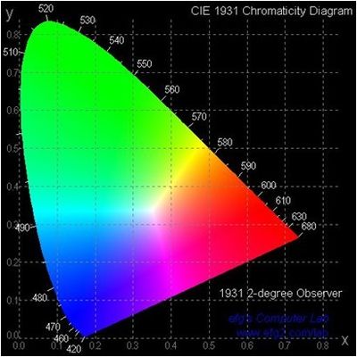
	Serial.println("Please reference the figure(Chromaticity Diagram) in the wiki ");
	Serial.println("so as to get the recommended color.");
  }
 else
 Serial.println("Error,the value overflow");
}
Extended ReadingThe color sensor uses the TCS3414CS color chip, which contains 4 channels: red (R), green (G), blue (B), blank (C), and the data of these 4 channels can be transformed into X and Y values. This transformation is based on the Internationale de l Eclairage Commission (CIE) standard.
The transformation is carried out by the following equation: Video |


