The Use of Crash Sensor
OutlineIt is used for detecting collision. Therefore it can also be called collision signal sensor. Due to different collision direction, we can divide Microduino-Crash into left-Crash and right-Crash.
Specification
DevelopmentEquipment
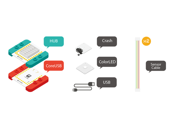
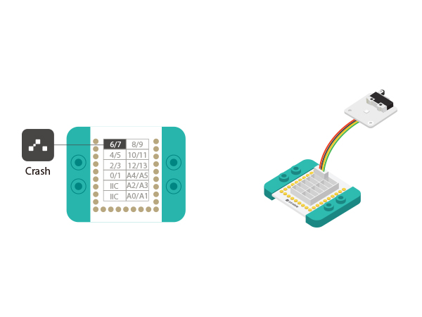
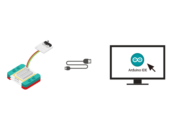
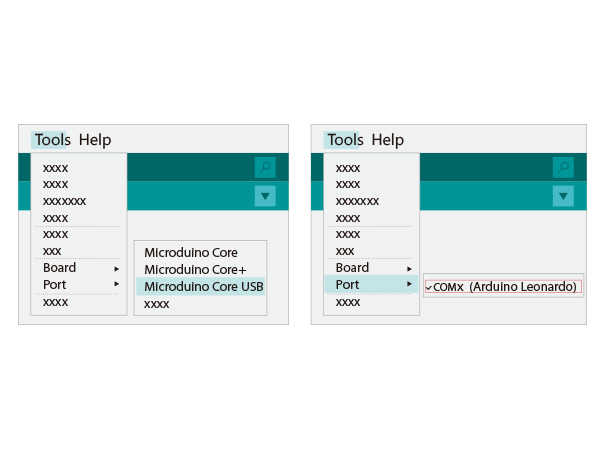
Preparation
DebuggingExperiment One: Key Detection
#define pushButton  6

int buttonState;

// the setup routine runs once when you press reset:
void setup() {
  // initialize serial communication at 9600 bits per second:
  Serial.begin(9600);
  // make the pushbutton's pin an input:
  pinMode(pushButton, INPUT);
}

// the loop routine runs over and over again forever:
void loop() {
  // read the input pin:
  buttonState = digitalRead(pushButton);//Read the input value of the Crash.
  // print out the state of the button:
  Serial.print("buttonState:");
  Serial.println(buttonState);  //Print the value in the serial port.
  delay(100);     // 100ms time delay
}
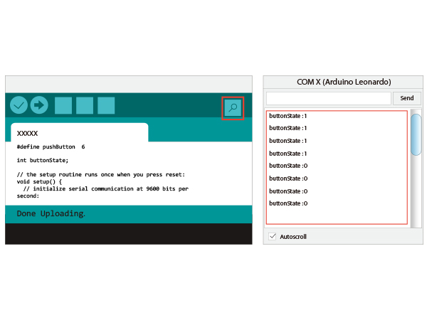
*Adopt " digitalRead(XX " to read the key signal, which is digital with the status of "0" or "1". Experiment Two: Press down or Release the Key
#define pushButton  6 //Define the control pin of the key.

int buttonState, num;

// the setup routine runs once when you press reset:
void setup() {
  // initialize serial communication at 9600 bits per second:
  Serial.begin(9600);
  // make the pushbutton's pin an input:
  pinMode(pushButton, INPUT);
}

// the loop routine runs over and over again forever:
void loop() {
  // read the input pin:
  buttonState = digitalRead(pushButton);//Read the input value of the Crash.
  // print out the state of the button:
  //Print the value when pressing down or releasing the key.
  if (num != buttonState)
  {
    num = buttonState;
    if (num == 1)
      Serial.println("Loosen");//Release
    else
      Serial.println("Control");//Press down
    delay(100);     // 100ms time delay
  }
}
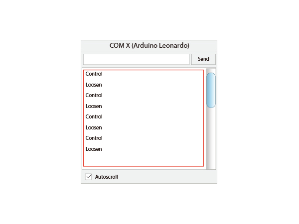
Experiment Three: Pressing status change
#define pushButton  6

int buttonState;

boolean str;

// the setup routine runs once when you press reset:
void setup() {
  // initialize serial communication at 9600 bits per second:
  Serial.begin(9600);//Serial communication baud rate
  // make the pushbutton's pin an input:
  pinMode(pushButton, INPUT);
}

// the loop routine runs over and over again forever:
void loop() {
  // read the input pin:
  buttonState = digitalRead(pushButton);//Read the input value of the Crash.
  if (!buttonState)
  {
    delay(300);
    str = !str;
    Serial.print("str:");
    Serial.println(str);
  }
}
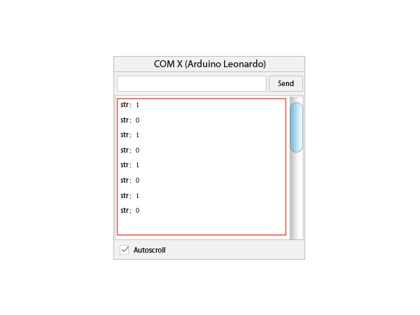
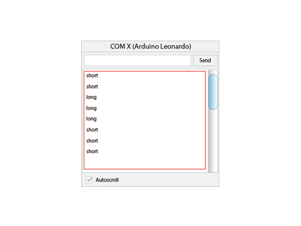
Press once, the "str" value is True(1) or twice, the value is False(1). Experiment Four: Short pressing & Long pressing function
#define pushButton  6

int buttonState, num;

unsigned long button_time_cache = 0;
unsigned long button_time = 0;

boolean button_sta = false;

void setup() {
  // initialize serial communication at 9600 bits per second:
  Serial.begin(9600);
  // make the pushbutton's pin an input:
  pinMode(pushButton, INPUT);
}

void loop() {
  // read the input pin:
  buttonState = digitalRead(pushButton);// Read the input value of the Crash.

  if (buttonState == 0)
  {
    delay(100);
    if (digitalRead(pushButton) == 1 && !button_sta)//Loosen the key and do not enter long pressing, meaning short pressing.
    {
      Serial.println("short");
    }
    else if (millis() - button_time_cache > 1500) //The pressing time is longer than 1.5s, meaning long pressing.
    {
      button_sta = true;
      button_time_cache = millis();
      Serial.println("long");
    }
  }
  else  if (buttonState == 1)
  {
    button_time_cache = millis();
    button_sta = false;
  }
}
Experiment Five: Colored Light Control
#define PIN_LED A0
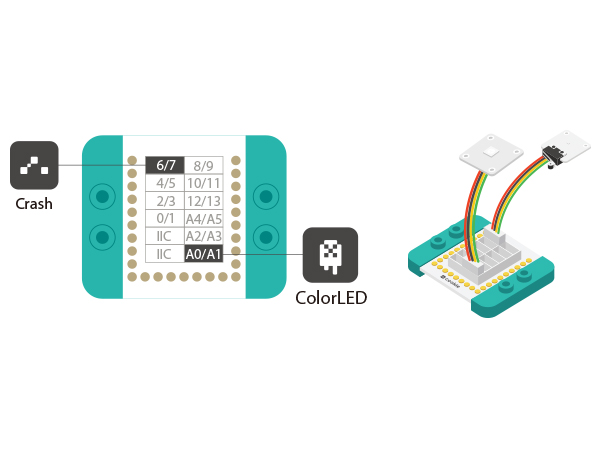
#define PIN_key 6

boolean status=false;

#include <Adafruit_NeoPixel.h>
Adafruit_NeoPixel strip = Adafruit_NeoPixel(6, PIN_LED, NEO_GRB + NEO_KHZ800);

void setup()
{
  pinMode(PIN_key, INPUT);
  pinMode(PIN_LED, OUTPUT);

  strip.begin();	// Initialize the LED
  strip.show(); // Initialize all pixels to 'off'
}

// the loop function runs over and over again forever
void loop()
{
  if(!digitalRead(PIN_key))
  {
    delay(100);
    if(!digitalRead(PIN_key))
    {
      status=!status;
    }
  }

  if(status)
  {
    colorWipe(strip.Color(0, 0, 0), 10);	//Close the light
  }
  else
  {
    colorWipe(strip.Color(255, 0, 0), 10);	//Blue
  }
}

// Fill the dots one after the other with a color
void colorWipe(uint32_t c, uint8_t wait)
{
  for(uint16_t i=0; i<strip.numPixels(); i++)
  {
    strip.setPixelColor(i, c);
    strip.show();
    delay(wait);
  }
}
Video |
