Open Source Smart Egg Demo System
ContentsOutline
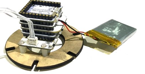
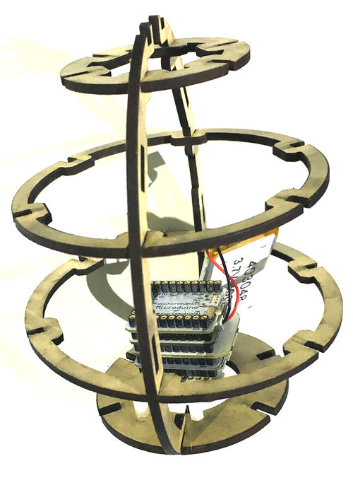
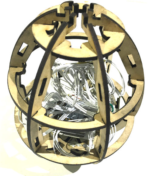
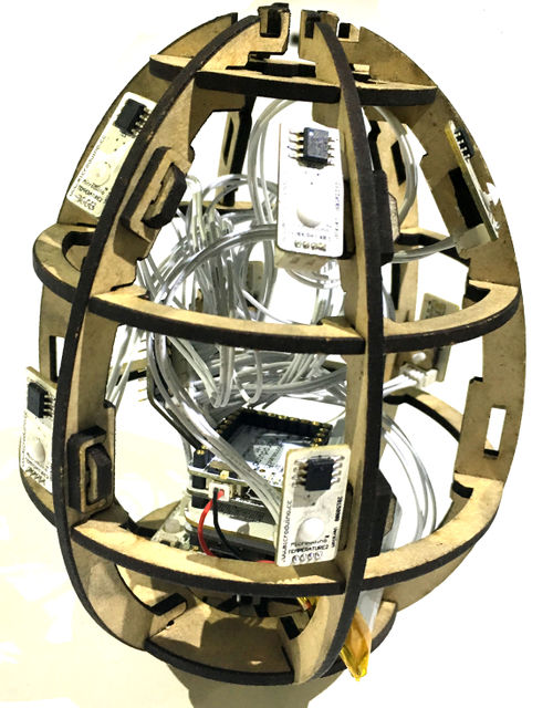
In this tutorial, we will use Microduino product module to build an egg temperature detection system. This system collect the content of every points of the egg through temperature sensor, and at the same time real time produce temperature representation. Bill of Material
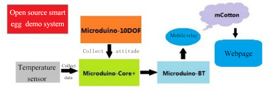
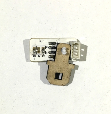
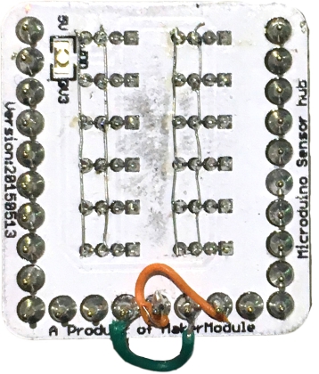
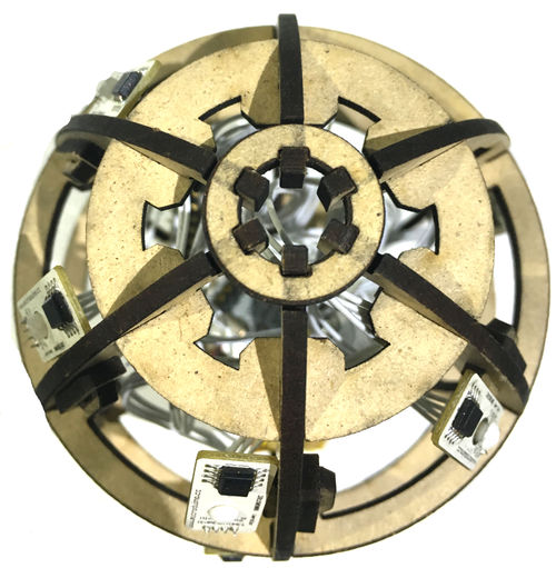
Principle of the ExperimentThe smart egg system is mainly composed of two large division. The data acquisition section is composed of 8 LM75 temperature sensor and a 10DOF module, and real time collect the temperature and position state of multiple points of the egg, then connect with the mobile phone through the Bluetooth module Microduino-BT after the processing of the Core+ and send the data to the mobile relay, then upload to our cloud server mCotton. Then we can view the temperature representation and the egg’s posture representation through the webpage.
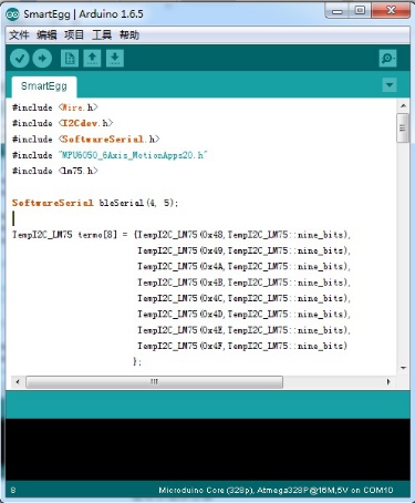
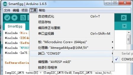
Microduino-LM75 Microduino-Motion DocumentsThe code of the egg:【Smart egg system code】 The code of the egg Github:SmartEgg Debug ProcessOverlay Microduino-Core+ and Microduino-USBTTL together, and upload the program that you have completed to Microduino-Core+ through Microduino-USBTTL with USB cable. Note:Please upload programs before stacking all modules together. Open the Arduino IDE programming software, and click [File]->[Open], then choose Microduino_Audio_ble\ SmartEgg.ino after opening the card speaker folder. Click "√", and programming. Click [Tool], and choose the right board + processor + port. Click "→", and upload. Assembly
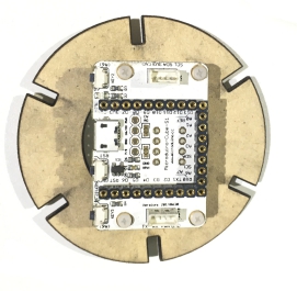
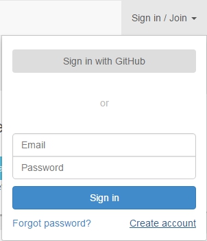
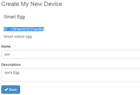
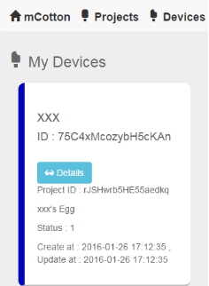
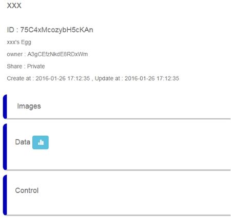
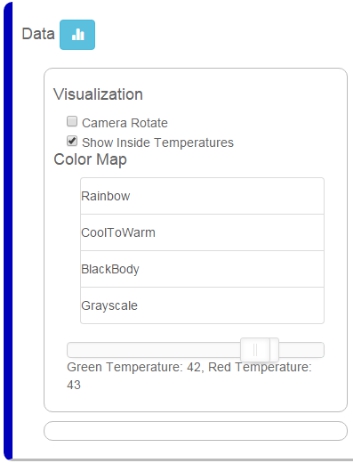
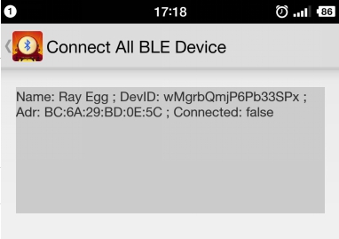
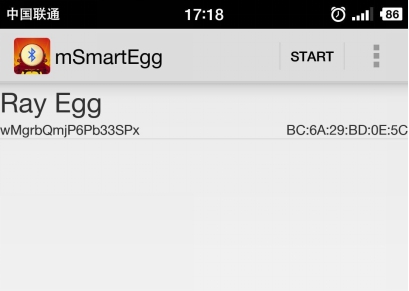
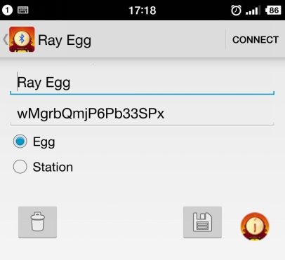
Now the egg portion is completed. MCotton SettingEnter https://mcotton.microduino.cn/projects Click Sign in/Join at top right corner, and click Create account at the bottom right corner in the drop-down menu to create your own account. Input Email as your username and password, then click Create. After registration, it will automatically enter login status. If you haven’t login in, click Sign in at the top right corner to input username(email)and password to login in, then click Projects at the top left corner. At this time, this page will display a number of labels. Find out Smart Egg label, and click Made It to enter the next page. Here fill out your project name and project description. You should keep the highlighted part ID in mind, and it is suggested to keep in a TXT to store. Then click √Save. Then enter myDevice page. You will see the project named as XXX( the name you just set), and click Details to enter the detail page. In the following page, click the blue icon on the right of Data to enter the observation page. If connect successfully, the egg’s data map will be displayed on the right, and on the left is the option setting part. Mobile RelayClick to open the phone APP to enter the following page The picture will show the existing project information, where the Connected is the communication state between the mobile and mCotton, and the next true/false is the connection state between the egg and the mobile phone blueooth. Then click Start button at the top right corner to enter the next step, at this time, click the button at the top right corner and choose Add Device. Input the name and the ID of the project which is recorded in mCotton steps, and click the CONNECT button at the top right corner. Now the settings of the mobile phone relay part is finished. After all steps have been completed, watch the phone relay part, if the state is Connect,true. If it is, then you can begin to view web page to observe the data. Operating InstructionProgram Specification#include <Wire.h>
#include <I2Cdev.h>
#include <SoftwareSerial.h>
#include "MPU6050_6Axis_MotionApps20.h"
#include <lm75.h>
SoftwareSerial bleSerial(4, 5);
TempI2C_LM75 termo[8] = {TempI2C_LM75(0x48, TempI2C_LM75::nine_bits),
TempI2C_LM75(0x49, TempI2C_LM75::nine_bits),
TempI2C_LM75(0x4A, TempI2C_LM75::nine_bits),
TempI2C_LM75(0x4B, TempI2C_LM75::nine_bits),
TempI2C_LM75(0x4C, TempI2C_LM75::nine_bits),
TempI2C_LM75(0x4D, TempI2C_LM75::nine_bits),
TempI2C_LM75(0x4E, TempI2C_LM75::nine_bits),
TempI2C_LM75(0x4F, TempI2C_LM75::nine_bits)
};
Quaternion q;
MPU6050 mpu;
uint8_t mpuIntStatus;
uint16_t packetSize;
uint16_t fifoCount;
uint8_t fifoBuffer[64]; // FIFO memory buffer
float buff1[10]; //Sen data cache.
unsigned long time_mpu, time_tem;
uint8_t devStatus;
//To obtain a quaternion.
void dmpGetQuaternion()
{
mpuIntStatus = mpu.getIntStatus();
fifoCount = mpu.getFIFOCount();
if((mpuIntStatus & 0x10) || fifoCount == 1024)
{
mpu.resetFIFO();
}
else if(mpuIntStatus & 0x02)
{
while (fifoCount < packetSize) fifoCount = mpu.getFIFOCount();
mpu.getFIFOBytes(fifoBuffer, packetSize);
fifoCount -= packetSize;
mpu.dmpGetQuaternion(&q, fifoBuffer);
// mpu.resetFIFO();
}
}
void setup()
{
Serial.begin(9600);
bleSerial.begin(9600);
Wire.begin();
mpu.initialize();
Serial.println("Testing device connections...");
Serial.println(mpu.testConnection() ? "MPU6050 connection successful" : "MPU6050 connection failed");
Serial.println(F("Initializing DMP..."));
devStatus = mpu.dmpInitialize();
if(devStatus == 0)
{
Serial.println(F("Enabling DMP..."));
mpu.setDMPEnabled(true);
mpuIntStatus = mpu.getIntStatus();
packetSize = mpu.dmpGetFIFOPacketSize();
}
else
{
while(1)
{
Serial.print(F("DMP Initialization failed (code "));
Serial.print(devStatus);
Serial.println(F(")"));
}
}
}
void loop()
{
dmpGetQuaternion();
if(millis() > time_mpu + 1000)
{
time_mpu = millis();
buff1[0] = q.w;
buff1[1] = q.x;
buff1[2] = q.y;
buff1[3] = q.z;
/*
Serial.print("quat\t");
Serial.print(q.w);
Serial.print("\t");
Serial.print(q.x);
Serial.print("\t");
Serial.print(q.y);
Serial.print("\t");
Serial.println(q.z);
*/
sendData(0xAA, 16, (uint8_t *)buff1);
}
if(millis() > time_tem + 5000)
{
time_tem = millis();
for(int i = 0; i < 8; i++)
{
buff1[i] = termo[i].getTemp();
Serial.print(buff1[i]);
Serial.print(",");
}
Serial.println(" ");
sendData(0xBB, 32, (uint8_t *)buff1);
}
}
void sendData(uint8_t cmd, int _num, uint8_t *_buf)
{
uint8_t sendBuf[40];
sendBuf[0] = 0xAA;
sendBuf[1] = 0xBB;
sendBuf[2] = cmd;
if(_num > 0)
memcpy(sendBuf + 3, _buf, _num);
sendBuf[_num+3] = 0x0d;
sendBuf[_num+4] = 0x0a;
bleSerial.write(sendBuf, _num + 5);
}video |
