Microduino Ward Calling System

From Microduino Wiki
Revision as of 03:57, 12 March 2015 by 1304410487@qq.com (talk) (Created page with "{| style="width: 800px;" |- | ==Purpose== The course will show you how to use Microduino to simulate a ward calling system. ==Equipment== {|class="wikitable" |- |Module|...")
(diff) ← Older revision | Latest revision (diff) | Newer revision → (diff)
Jump to: navigation, search


Purpose

The course will show you how to use Microduino to simulate a ward calling system.

Equipment

Module Number Function
Microduino-Core 2 Core board
Microduino-Core+ 1 Core board
Microduino-OLED 1 For display
Microduino-Cube-S1 1 Extension board
Microduino-USBTTL 2 Program download
Microduino-nRF24 3 Wireless network
Microduino-Amplifier 1
Microduino-SD 1 Audio storage


  • Other Equipment
10KΩ resistor Two
Breadboard jumper wire One box
micro usb cable One
Button Two
Breadboard One
Loudspeaker One

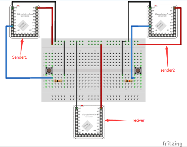
Schematic

HospitalCallSechmatic.png

There are two senders—sender 1 and sender 2 in the picture—for patients to send signals.

Modules to be stacked:

  • Microduino-Core
  • Microduino-USBTTL
  • Microduino-nRF24

One receiver for nurses to check for patient help.

  • Microduino-Core+
  • Microduino-USBTTL
  • Microduino-nRF24
  • Microduino-Cube-S1
  • Microduino-OLED

Program

[MicroduinoHospitalCall]

Debugging

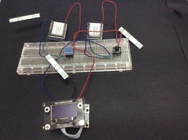
Step 1: Build the circuit according to schematic, as follows:

HospitalCall1.png


Step 2: Download code and compile.

HospitalCall2.png


Step 3: Supply power to any of the three stacked Microduino modules and the whole stacked system will be powered.

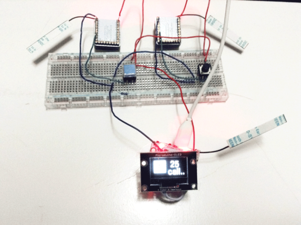
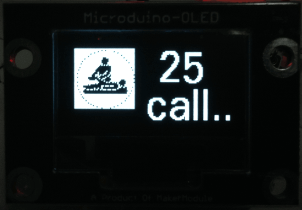
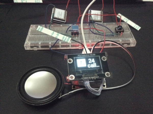
Meantime, press button marked with sender 2 in the schematic and the readings will be displayed on receiver OLED:


HospitalCall3.png

If readings showed on OLED were defined in the code, it means the calling of No. 25 patient is successful.


Then press the button of sender 1, the calling of No. 24 patient is successful.

The 16 hexadecimal of the picture showed on OLED is produced through PCtolCD. The detailed method can refer to: Lesson 2--Microduino OLED Usage

Step 4: By adding voice prompt function, medical workers can get voice notice when someone calls.

Stack Microduino-Amplifier and Microduino-SD on the basis of the three modules, as follows:

HospitalCall3Sound.png

Re-download MicroduinoHospitalCallReciverSound.ino program to Core+. Save audio files you want to play into SD card of Microduino-SD. As for how to make audio files, please refer to: Microduino LM4863 Music player -301KIT


Step 5: since the three devices (Sender1, Sender 2 and Receiver) are far to each other, so we can consider to power on them with Microduino-BM.

Result

Here we make a simple wireless ward calling system.

Video

http://v.youku.com/v_show/id_XODUxNzM3OTYw.html