Smart Garbage Can
Contents[hide]Outline
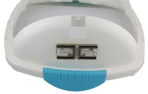
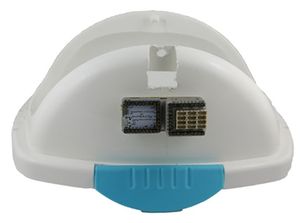
Feeling the closing action of human body, within the measurable scope with distance measurement sensor, the collected infrared intensity will affect its own resistance and to change the output voltage value. The processor decides whether to open the garbage can or not and the direction to open to accept the rubbish through judging the output voltage. Bill of Materials
Principle of the Experiment
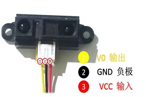
Sharp 2y0a21 model measurement sensor is a distance measurement sensor based on PSD. Through changing the resistance according to the temperature of the outside environment by its thermal resistance in the circuit, change the voltage of both ends of the sensor. But the there is a certain scope that the thermal resistance measures the distance according the change of the temperature, and the measuring scope of sharp 2y0a21 is 10~80cm. Within the scope of around 0~8cm, the temperature is proportional nonlinear relationship with the distance, and within the scope of around 10~80cm, it is proportional inverse nonlinear relation with the distance, and the mean consumption is around 30mA, and the reaction time is around 5ms, and it has a strong adaptability to the background and the temperature. The effective measurement angle is bigger than 40 degrees, and the output signal is analog voltage.
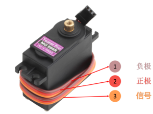
The steering engine is a kind of deck machinery on ship. The size of the steering gear depends on the outfitting according to the standard of classification society. When select the shape, you should mainly consider the torque size. The steering gear is widely used in aerospace. In the field of space, the pitching, yawing, and rolling motions of missile attitude transformation are done with the cooperation of the steering gear. Steering gear is used in many engineering applications, not just limited in the ship. Steering gear is mainly composed of the shell, circuit board, no-core motor, gears and position detector. Its work principle is that the receiver sends signal to the steering gear, and through the judgment of rotation of the IC on the circuit board, drive the no-core motor to start turning, and transmit the power to the swing arm through the reduction gear, at the same time, the position detector returns signal to judge whether it has reached the position. The maximum rotation angle of MG996R is 180 degrees. When programming, the rotating angle range is(0~180 degrees).
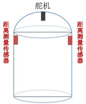
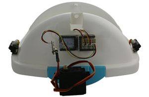
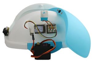
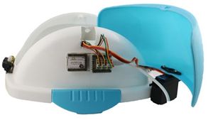
The distance measurement sensor induces the infrared intensity on both sides, and send the value to the core chip. The core chip determines the rotating angle of the steering gear through dueling with this data, to determine whether the garbage should open the door, and which door to open. Because the rotating angle of the steering gear is 0~180 degree, you'd better place the equilibrium position in the center of the rotating angle of the steering gear. The principle diagram of the installation of the garbage can
Distance measurement sensor The characteristics of the distance measurement sensor
MG996R steering gear The circuit description of the MG996R steering gear, as shown in the picture. The characteristics of(MG996R).
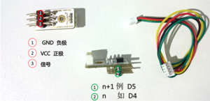
The attachment pin of Microduino servo-cin. In this program, define the pins of the steering gear, corresponding to one pin in one Microduino-Sensorhub slot (there are two pins in one slot), and the farer end away from the board is the pin with smaller number. DocumentDebugging
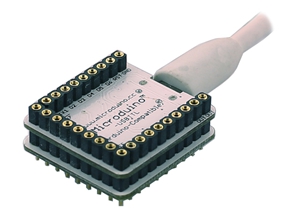
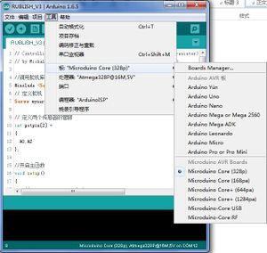
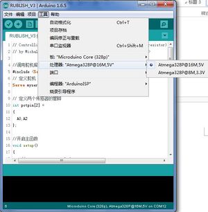
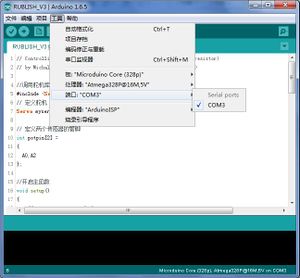
Stack Microduino Core and Microduino USBTTLtogether, and use USB cable to upload the completed program to Microduino Core through Microduino USBTTL. Note: You'd better upload program before stacking all modules together.Open the program, and click the program to compile. After the success of the compilation, choose【port】, 【board】 and 【processor】in 【Tool】. After choosing【board】 and 【processor】, click to upload. The choice of the board The choice of the processor The choice of the port
Fix Microduino-Duo-v with screws on the garbage can.
Stack modules, and stack Microduino-Core, Microduino-USBTTL, Microduino-BM, Microduino-Duo-v, and Microduino-Sensorhub together(no order).
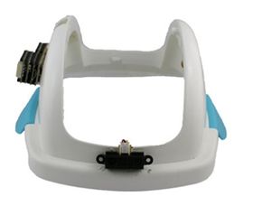
Install the measurement sensor Place the measurement sensors on both sides of the garbage can. When fixing, there should be a certain angle between it and the wall. ( around 45 degrees).
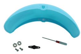
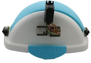
Fix the word arm on the door of the garbage can.
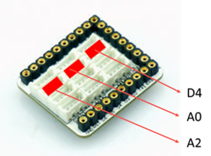
Connect the circuit The instruction of the pins of the slot that the Microduino-Sensorhub needs to connect to.
Connect the measurement sensor on the left of the module to A0, and the right to A2. After connecting the steering gear and Microduino servo-cin, connect the connecting line to D4 slot of Microduino-Sensorhub.
Install the steering gear Make the rotating axis of the steering gear rotate to the medium(avoiding it rotating only to a direction after being installed). The door of the garbage can is a rotary switch. Place the steering gear and fix it on the rotating axis, to make the rotation of the steering gear spins the door of the garbage can.
System testing Connect the computer and the USB interface of the USB board with USB cable, and test the measurement sensors on both sides. Modify the rotating angle of the steering gear in the program, adjust the rotating angle and direction of the steering gear to make it can control the opening direction of the steering gear through the human body induction. The function of debugging the direction of the steering gear is myservo.write(). Just set the rotating angle of the steering gear in the brackets of the function. Note: In the program, the angle can/t be written into negative. Program Description
#define sensor_vol 300  //sensor_vol  core input (the sensor inputs)bigger that this value:hand approaching;smaller that this value:no hand near
#define servo_vol 93  //The angle that the steering gear rotates to.

/*Why is it 300?
  The output value of the infrared distance sensor is an analog quantity between 0~5V. The closer the measurement is, the higher the voltage is.
  This analog is (0~5V)input into A0 and A2 ports of the core module(two analog input ports). Make it convert into the quantity that the compute is able to identify, through the AD converter(ADC), which is called as digital quantity. The digital quantity is 0~1023(5V<-->1023, different ADC has different measurement range).

Conversion relation:
        Input voltage    |   The quantity of the numbers used in the computer.
        V    |    V*1023/5.

  According to the measurement, when there is no hand approaching, the output voltage of the infrared sensor is 0.3V, and the corresponding number quantity is 0.3*1023/5=61.38 .
 When there is hand approaching, the output voltage is 1.6V, and the corresponding number quantity is 1.6*1023/5=61.38=327.36.
  Choose one between the two as the standard to judge whether there is a hand approaching.
Think about that can it be changed into 200? Have a try.
*/

int potpin[2] =
{
    A0, A2
};  //Define the input pins of the sensor.

#include "key.h"

#include <Servo.h> //Since the steering gear is used, we should load the library file for it. This library file contains various operating instruction for the steering gear, such as myservo.write().
Servo myservo;  // create servo object to control a servo

int val[2] = {0, 0}; // variable to read the value from the analog pin
//The array, is used to store the input values in the two analog input ports(it has been converted to the number between 0~1023).

boolean sta[2] =
{
    false, false
};//Status flag. False represents the lid is closed, and true represents the lid is open.
//Two elements are used because the lid can be open on both side.

void setup()
{
    Serial.begin(9600);//Set up the serial port rate to be used to communicate with the computer by serial ports.
    pinMode(potpin[0], INPUT);
    pinMode(potpin[1], INPUT);
    myservo.attach(4);  //Set the steering gear's pin as D4 .
    myservo.write(servo_vol);                  // //When the steering gear rotates to the angle the servo_vol shows, the  garbage can closes the lid.
    key_init();
}

void loop()
{
    //------0---------------------------------------------------------------
    val[0] = analogRead(potpin[0]);            //The output voltage that is read into the sensor 0 reads the value of the potentiometer (value between 0 and 1023)

    if((val[0] > sensor_vol) && (sta[0] == false)) //When this voltage > threshold value(there is hand approaching the garbage can) and at this time the lid is closed, open the lid positively.
    {
        Serial.println("sta[0]!");
        Serial.println("UP");
        myservo.write(180);                  // sets the servo position according to the scaled value
        sta[0] = true;
        delay(1000);
    }


    if((val[0] < sensor_vol) && (sta[0] == true)) //When this voltage < threshold value(there is no hand approaching) and at this time the lid is open, close the lid.
    {
        Serial.println("DOWN");
        myservo.write(servo_vol);
        sta[0] = false;
        delay(1000);
    }

    /*Why need to add sta?
      The loop function is implemented in cycle. If it is only "rotating when the senor is covered by hand", when the sensor is covered all the time, the lid will constantly reverse.
      So our logic must be when"the hand cover the sensor" and "at this time the lid is closed",it reverses.
    */

    //------------------------------------
    val[1] = analogRead(potpin[1]);            // reads the value of the potentiometer (value between 0 and 1023)

    if((val[1] > sensor_vol) && (sta[1] == false))
    {
        Serial.println("sta[1]!");
        Serial.println("UP");
        myservo.write(0);                  // sets the servo position according to the scaled value
        sta[1] = true;
        delay(1000);
    }


    if((val[1] < sensor_vol) && (sta[1] == true))
    {
        Serial.println("DOWN");
        myservo.write(servo_vol);
        sta[1] = false;
        delay(1000);
    }
}
#include "arduino.h"

boolean key_status[NUM_DIGITAL_PINS];            //The keys
boolean key_cache[NUM_DIGITAL_PINS];        //Detect the button is released and cache.

void key_init()
{
    for(int a = 0; a < NUM_DIGITAL_PINS; a++)
    {
        key_status[a] = LOW;
        key_cache[a] = HIGH;
    }
}

boolean key_get(int _key_pin, boolean _key_type)
{
    key_cache[_key_pin] = key_status[_key_pin];        //The cache for judgment

    key_status[_key_pin] = analogRead(_key_pin) > sensor_vol;    //When the trigger

    switch(_key_type)
    {
    case 0:
        if(!key_status[_key_pin] && key_cache[_key_pin])        // After the press releases
            return true;
        else
            return false;
        break;
    case 1:
        if(key_status[_key_pin] && !key_cache[_key_pin])        //After the press releases
            return true;
        else
            return false;
        break;
    }
}
Video |
