Voice Control Light
Contents[hide]Outline
In this tutorial, we adopt Microduino modules to build a light control system controlled by human voice. Users can talk to the device and control the illumination and color of the light module. Bill of Material
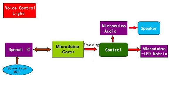
PrincipleThe principle of the Voice Control Light is to record the one-to-one mapping relationship of the voice and scene. The input voice will be firstly recognized, then it will return the scene number to the core module, which will control the illumination of the light via the analog port and realize color combination under different scenes. The whole light control system consists of four parts:
Adopt [Microduino-BM] battery module and the external battery combination as the power supply for the Voice Control Light.
The CPU of the Voice Control Light adopt Microduino-Core+ as the core.
The Voice Control Light adopts Bluetooth wireless communication. With the [Microduino-BT(4.0)] module, the communication response speed is fast. Additionally, the control range of the light is about eight meters.
Collect and recognize the voice content.
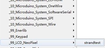
The project adopts Microduino-LED Matrix as luminous device. This module cascades six RGB lights and use the corresponding library function to control the color of each light. In order to illustrate the control method of the Microduino-LED Matrix, we have a simple program example. Open Arduino IDE and the "strandtest" under (File) —> (Examples) —>_99_LCD_NeoPixel. #include <Adafruit_NeoPixel.h>
#define PIN 6 //Define the control pin
// Para.1 = Number of the colored lights in the strip
// Para.2= Number of the pins
//Para3=Type of the colored lights (For option)
// NEO_RGB Pixels are wired for RGB bitstream
// NEO_GRB Pixels are wired for GRB bitstream
// NEO_KHZ400 400 KHz bitstream (e.g. FLORA pixels)
// NEO_KHZ800 800 KHz bitstream (e.g. High Density LED strip)
Adafruit_NeoPixel strip = Adafruit_NeoPixel(60, PIN, NEO_GRB + NEO_KHZ800);
void setup()
{
strip.begin();
strip.show(); //Initialize all the colored lights
}
void loop()
{
// Way to get lightened
colorWipe(strip.Color(255, 0, 0), 50); // Red
colorWipe(strip.Color(0, 255, 0), 50); // Green
colorWipe(strip.Color(0, 0, 255), 50); // Blue
rainbow(20);
rainbowCycle(20);
}
//Lighten the lights with the color represented by "c".
void colorWipe(uint32_t c, uint8_t wait)
{
for(uint16_t i = 0; i < strip.numPixels(); i++) //Get them lightened in order.
{
strip.setPixelColor(i, c); //The function is used for lightening the "i" light with the color of "c".
strip.show(); //This function will show control info. written by "setPixelColor" function
delay(wait);
}
}
void rainbow(uint8_t wait) //Rainbow display
{
uint16_t i, j;
for(j = 0; j < 256; j++) //225 kinds of color
{
for(i = 0; i < strip.numPixels(); i++) //Lighten the lights in order
{
strip.setPixelColor(i, Wheel((i + j) & 255));
}
strip.show();
delay(wait);
}
}
// Different from the function above, it adds the loop of the rainbow color.
void rainbowCycle(uint8_t wait)
{
uint16_t i, j;
for(j = 0; j < 256 * 5; j++) //The rainbow color repeats for five times.
{
for(i = 0; i < strip.numPixels(); i++)
{
strip.setPixelColor(i, Wheel(((i * 256 / strip.numPixels()) + j) & 255)); //Mathematical manipulation added for the loop.
}
strip.show();
delay(wait);
}
}
// Input any number of 0-225 and get the corresponding color.
// The color will change from red, green to blue and red in loop.
uint32_t Wheel(byte WheelPos)
{
if(WheelPos < 85)
{
return strip.Color(WheelPos * 3, 255 - WheelPos * 3, 0);
}
else if(WheelPos < 170)
{
//Since WheelPos * 3 will surpass 255 under 85 to 170, it needs to minus 85 firstly.
WheelPos -= 85;
return strip.Color(255 - WheelPos * 3, 0, WheelPos * 3);
}
else
{
// Since WheelPos * 3 will surpass 255 under 170 or more, it needs to minus 170 firstly.
WheelPos -= 170;
return strip.Color(0, WheelPos * 3, 255 - WheelPos * 3);
}DocumentDebugging
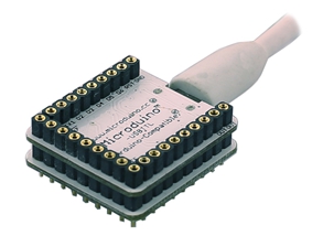
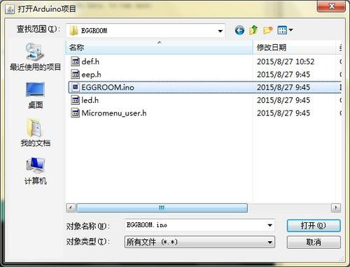
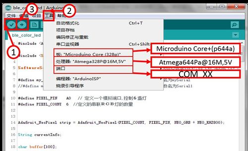
Stack Microduino-Core+ and Microduino-USBTTL together, and upload the program to the Core+ module through the UBSTTL module. Attention: Please upload the program before stacking all modules together. Find the program in "Voice Control Light/EGGROOM/EGGROOM.ino" and double click. Program download Click "√" and compile the program. Click【Tool】 and select the right board, processor and the port. Click"→" and upload.
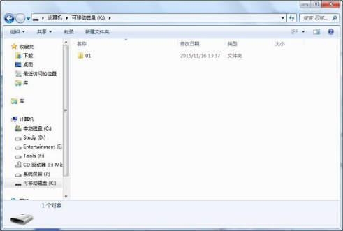
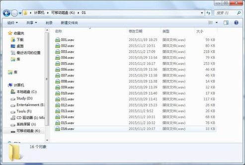
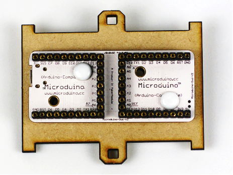
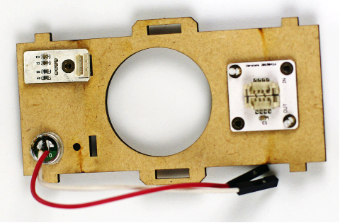
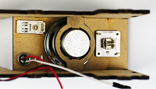
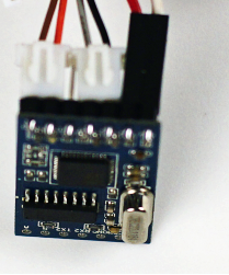
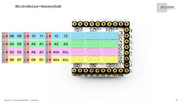
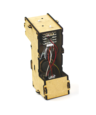
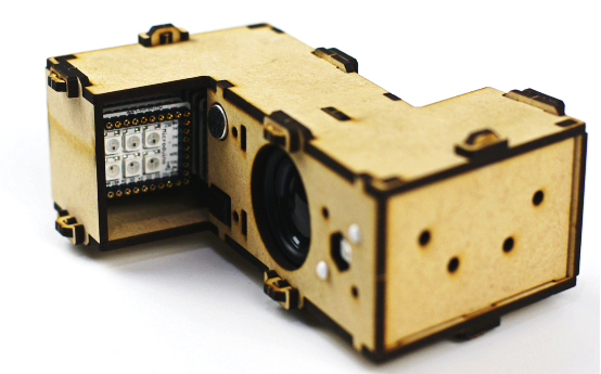
Insert the TF card into the Audio module, then connect the module to the computer with a USB cable. You'll see a removable disk. In the identified disk, the new folder is named as "01". Then, copy audio files into the folder according to the number order of the names. Here we save the audio files successfully. BuildupFixate Microduino-DUO-v on the top board . (The top and the bottom panels are the same. You can pick one as the top board. ) Build the hardware circuit and stack all devices needed. Microduino-Amplifier Microduino-Audio Microduino-sensorhub The modules above are put on one side of Duo-v. Microduino-Duo-V The modules below are put on the other side of Duo-v. Microduino-LED Matrix Microduino-Core+ Microduin-USBTTL Notes: Microduino-DUO-V as the base board can reduce the height of the structure, on which the LED Matrix module can be stacked. Microduino-LED Matrix and Microduino-Sensorhub can be put on the two sides of the base board. (It's suggested to install the Sensorhub before stacking other modules. ) As the figure shown below, you can fixate the Microduino-Temp&Hum, Microduino-Sound and Microduino-LED Matrix sensors on the front board. As the picture shows, you can fixate the speaker on the side board and left the connector cable leftwards for ease of installation. For the connection of the Microduino-Sound module, please refer to the picture below. Attention: If you want to use the USBTTL and the Sensorhub module to test the sound module, you have to make sure the connection of the RX and TX sides must be opposite to that shown in the picture above. Please refer to the picture above and connect the sensor cable of the Microduino-LED Matrix to the A2 port, the Temp&Hum sensor to the lower right interface of SDASCL, the Sound module to the D2/D3 interface. After the connection, please insert the Sensorhub in the top of the Audio module. By this step, all sensors have been connected to the Sensorhub and all modules stacked on the base board and the speaker fixated on the side board. Fixate the structure after the installation. Overall DebuggingPower on the Voice Control Light and wait for 2-3s and turn off. At this time, you can speak "Microduino" towards the Sound module, which is the open and close statement for the voice input. After that, you can see the voice input indicator (LED Matrix) goes on. Then, you can speak instructions and it takes 5s to speaker the next after the last instruction. If there is no voice input, the indicator will go out and you need to say "Microduino" again to enter the voice input status. The switch instruction in this example is "Microduino", so please say "Microduino" clearly and observe the LED Matrix. If it goes on, please continue your instruction, such as "tell a story", the LED will be lightened. If there is no response "Hi, I'm Microduino", then you can repeat to say "Microduino" until the LED gets lightened and hear the audio response. Notes
Program Description
void writecommand()
{
    VOICE.println("{d1}");
    delay(200);
    VOICE.println("{d1}");    //Make sure to enter the debugging mode
    delay(200);
    VOICE.println("{c0}");      //Clear current instructions
    delay(200);
    VOICE.println("{a0Microduino|s0pp}");  //Start the voice instruction
    delay(200);
    VOICE.println("{a0your name|s0mz}"); //You name
    delay(200);
    VOICE.println("{a0your age|s0nl}");  // You age
    delay(200);
    VOICE.println("{a0tell a story|s0gs}");   //Tell a story
    delay(200);
    VOICE.println("{a0tell a poem|s0sg}"); //Tell a poem
    delay(200);
    VOICE.println("{a0happy |s0sm}"); //Happy
    delay(200);
    VOICE.println("{a0weather |s0wd}"); //Weather
    delay(200);
    VOICE.println("{a0dark|s0kd}");  //Dark
    delay(200);
    VOICE.println("{a0turn off the light|s0gd}");  //Turn off the light
    delay(200);
    VOICE.println("{a0goodbye|s0zj}");  //Goodbye
    delay(200);
    VOICE.println("{a0thank you|s0xx}");  //Thank you
    delay(200);
    VOICE.println("{l0}");     //Load
    delay(200);
    VOICE.println("{d0}");    //Stop debugging
    delay(200);
}
if (VOICE.available())
{
    String cmd = "";
    if (VOICE.available()) //If receiving user's voice input data from the voice chip
    {
        cmd += char(VOICE.read()); //Read content in the serial port
        delay(10);
        cmd += char(VOICE.read());
        delay(10);
    }
}
case 5:                       //Weather
timer_voice = 0;        //Reset the timer
am2321.read();           //Read the sensor
temperature = am2321.temperature / 10.0;
Serial.println(temperature);    //For debugging
if(temperature < 20)AUDIO.choose(15);   //Play different audio according to temperature
if(temperature >= 20 && temperature < 27)AUDIO.choose(14);
if(temperature >= 27)AUDIO.choose(16);
timer_voice = millis();            //Synchronize the time
break;
Video |
