Difference between revisions of "Sensor-Relay"
From Microduino Wiki
m (Fengfeng moved page Microduino-Relay to Sensor-Relay) |
(→Introduction of Pins) |
||
| (3 intermediate revisions by one other user not shown) | |||
| Line 5: | Line 5: | ||
[[File: Microduino-Relay.jpg|400px|thumb|right| Microduino-Relay]] | [[File: Microduino-Relay.jpg|400px|thumb|right| Microduino-Relay]] | ||
| − | + | The product number of Sensor-Relay is: '''MSD011'''. Sensor-Relay is a relay module. It can be used in isolation control. | |
| − | |||
| Line 16: | Line 15: | ||
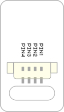
| + | ==Introduction of Pins== | ||
| + | {{ST_Pinout | ||
| + | |st_name=Servo Relay | ||
| + | |pin3=Digital Output | ||
| + | }} | ||
==Features== | ==Features== | ||
*Used in isolation control of high voltage and high current signal. | *Used in isolation control of high voltage and high current signal. | ||
| + | *With small size which is easy to install. | ||
==Specification== | ==Specification== | ||
| − | * | + | *Voltage |
| − | * | + | **Primary side input 5V working voltage |
| − | *1.27mm- | + | **Secondary side output 10A 250VAC/10A 30VDC |
| − | * | + | |
| − | + | *Size | |
| + | **Size of the board: | ||
| + | **1.27mm-spacing 4Pin interface connected with sensorhub | ||
| + | |||
| + | *Function description | ||
| + | **Use relay to control the output of a larger voltage. | ||
| − | + | *Connection | |
| + | **This sensor can be connected to the following interfaces of core: '''D2~D13''','''A0~A7''' | ||
==Document== | ==Document== | ||
| − | *Schematic: '''[[File: | + | *Schematic diagram: '''[[File: Sensor-Relay.Zip]]''' |
==Development== | ==Development== | ||
| − | + | ===Program Download=== | |
| + | *Download and unzip the program '''[[File:Sensor-Relay_Test.zip]]''' | ||
| + | |||
| + | ===Programming=== | ||
| + | {{Upload | ||
| + | |nameA=[[Microduino-Core]], [[Microduino-USBTTL]] | ||
| + | |nameB=[[Microduino-USBTTL]] | ||
| + | |boardName=Microduino/mCookie-Core(328p), Atmega328P@16M,5V | ||
| + | |fileName=Sensor-Relay Test.ino | ||
| + | }} | ||
| + | |||
| + | ===Hardware Setup=== | ||
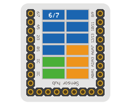
| + | *Referring to the following diagram, connect the Sensor-Relay to the digital pin D6 of '''[[Microduino-Sensorhub]]'''. | ||
| + | <br> | ||
| + | [[file:Microduino-sensorhub_Shake.JPG|thumb|400px|left]] | ||
| + | <br style="clear: left"/> | ||
| + | |||
| + | ===Result=== | ||
| + | *After download, you can see the STA light on the Relay module flash with 1s interval. Using a multimeter to measure the 2PIN crimping terminal on the Relay module, you can see the 2PIN terminal also be on-off with 1s interval. | ||
| + | |||
| − | |||
| − | |||
| − | |||
| − | |||
| − | |||
| − | |||
| − | |||
| − | |||
==Purchase== | ==Purchase== | ||
| − | |||
==Pictures== | ==Pictures== | ||
| − | + | {| border="0" cellpadding="10" width="100%" | |
| − | [[file: Microduino-Relay-F.JPG|thumb| | + | |- |
| − | + | |width="50%" valign="top" align="left"| | |
| − | [[file: Microduino-Relay -b.JPG|thumb| | + | [[file: Microduino-Relay-F.JPG|thumb|400px|center|Sensor-Relay Front]] |
| + | |width="50%" valign="top" align="left"| | ||
| + | [[file: Microduino-Relay -b.JPG|thumb|400px|center|Sensor-Relay Back]] | ||
| + | |} | ||
|} | |} | ||
Latest revision as of 23:39, 30 March 2017
| Language: | English • 中文 |
|---|
|
The product number of Sensor-Relay is: MSD011. Sensor-Relay is a relay module. It can be used in isolation control.
ContentsIntroduction of Pins
Features
Specification
Document
DevelopmentProgram Download
Programming
Hardware Setup
Result
PurchasePictures
|


