Difference between revisions of "Open Source Welcome Door Report"
From Microduino Wiki
(→Principle of the Experiment) |
(→Installation) |
||
| Line 86: | Line 86: | ||
*After all these items are correct, click '''"→"''' button to download the program to the development board. | *After all these items are correct, click '''"→"''' button to download the program to the development board. | ||
| − | == | + | ==Assembly== |
{| border="0" cellpadding="10" width="100%" | {| border="0" cellpadding="10" width="100%" | ||
|- | |- | ||
|width="50%" valign="top" align="left"| | |width="50%" valign="top" align="left"| | ||
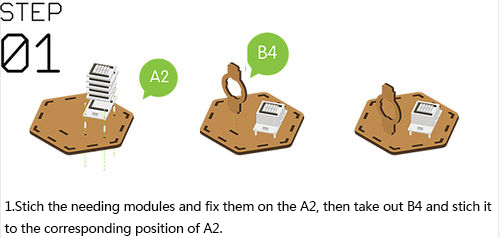
*'''Step1''': | *'''Step1''': | ||
| − | **'''As the following | + | **'''As the following figure shows''', fix '''[[Microduino-Cube-S1]]''' on the floor '''structure A2''' with '''nylon screws''' and '''nylon studs''' . |
| − | + | **Stack the modules on the floor '''[[Microduino-Cube-S1]]''' in the following order. | |
| − | |||
| − | |||
| − | |||
| − | |||
| − | |||
| − | |||
| − | |||
| − | |||
| − | ** | ||
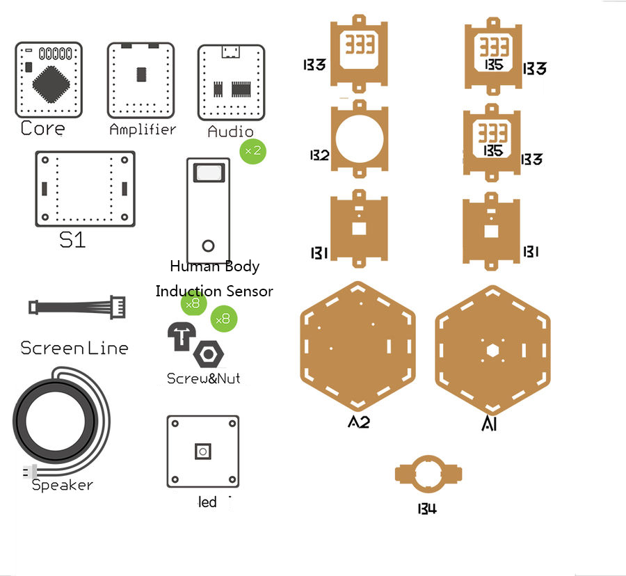
***'''[[Microduino-Core]]''' | ***'''[[Microduino-Core]]''' | ||
***'''[[Microduino-USBTTL]]''' | ***'''[[Microduino-USBTTL]]''' | ||
| Line 107: | Line 98: | ||
***'''[[Microduino-Amplifier]]''' | ***'''[[Microduino-Amplifier]]''' | ||
***'''[[Microduino-Sensorhub]]''' | ***'''[[Microduino-Sensorhub]]''' | ||
| + | **Then take out '''structure B4''' and join in the corresponding position of '''structure A2'''. | ||
|width="50%" valign="top" align="left"| | |width="50%" valign="top" align="left"| | ||
| − | [[File: | + | |
| + | [[File:Welcome11.jpg||500px|center|thumb]] | ||
|} | |} | ||
{| border="0" cellpadding="10" width="100%" | {| border="0" cellpadding="10" width="100%" | ||
|- | |- | ||
|width="50%" valign="top" align="left"| | |width="50%" valign="top" align="left"| | ||
| − | *''' | + | *'''Step2''': |
| − | ** | + | **'''As the following figure''', insert '''structure B6''' into the '''baseboard''' and fix the horn. |
| − | **''' | + | **Use '''nylon screws''' and '''nylon nuts''' to fix the two sensors '''[[Microduino-PIR]]''' on the two '''structure B1''' respectively. |
| − | **Insert '''structure | + | **Insert '''structure B1''' into the '''baseboard'''. |
| + | **Connect the '''horn''' to the interface of the module '''[[Microduino-Amplifier]]'''(no difference sequence). | ||
|width="50%" valign="top" align="left"| | |width="50%" valign="top" align="left"| | ||
| − | [[File: | + | [[File:Welcome21.jpg||500px|center|thumb]] |
|} | |} | ||
{| border="0" cellpadding="10" width="100%" | {| border="0" cellpadding="10" width="100%" | ||
|- | |- | ||
|width="50%" valign="top" align="left"| | |width="50%" valign="top" align="left"| | ||
| − | + | ||
| − | * | + | *Connect the two sensors '''[[Microduino-PIR]]''' to the interfaces '''D4/D5''' and '''D6/D7'''('''which are marked in blue in the figure'''). |
| − | * | + | *Connect '''[[Microduino-Color led]]''' to the '''A0/A1''' interface ('''which is marked in red in the figure'''). |
|width="50%" valign="top" align="left"| | |width="50%" valign="top" align="left"| | ||
| − | [[File: | + | [[File:Welcome6.jpg||500px|center]] |
|} | |} | ||
{| border="0" cellpadding="10" width="100%" | {| border="0" cellpadding="10" width="100%" | ||
|- | |- | ||
|width="50%" valign="top" align="left"| | |width="50%" valign="top" align="left"| | ||
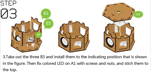
| − | *''' | + | *'''Step3''': |
| − | **'''As | + | **'''As the following figure''', insert the 3 '''structure B3''' into the '''baseboard''' ('''structure A2'''). |
| + | **'''As the following figure''', use '''nylon screws''' and '''nylon studs''' to fix '''[[Microduino-Color led]]''' on the '''top cap(structure A1)'''. | ||
|width="50%" valign="top" align="left"| | |width="50%" valign="top" align="left"| | ||
| − | [[File: | + | [[File:Welcome331.jpg||500px|center|thumb]] |
|} | |} | ||
{| border="0" cellpadding="10" width="100%" | {| border="0" cellpadding="10" width="100%" | ||
|- | |- | ||
|width="50%" valign="top" align="left"| | |width="50%" valign="top" align="left"| | ||
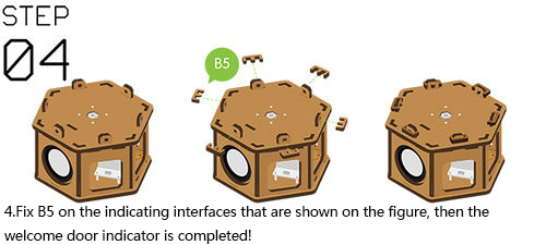
| − | *''' | + | *'''Step4''': |
| − | **''' | + | **Fix '''structure B5''' on the indicating interfaces as the figure shows, and the welcom door detector is completed. |
| − | |||
| − | |||
| − | |||
| − | |||
| − | |||
| − | |||
| − | |||
| − | |||
| − | |||
| − | |||
| − | |||
| − | |||
|width="50%" valign="top" align="left"| | |width="50%" valign="top" align="left"| | ||
| − | [[File: | + | [[File:Welcome41.jpg||500px|center|thumb]] |
|} | |} | ||
Revision as of 02:37, 17 June 2016
ContentsOutline
Bill of Material
Principle of the Experiment
Program Download
Programming
Assembly
Operating Instruction
The Instruction of the Code
{
    //First passing D4, then passing D6 is entering.
    if((digitalRead(body_pin) == 1) && (digitalRead(body_pin2) == 0))
    {
        FLAG_1 = 1;
        delay(200);
    }
    if((digitalRead(body_pin) == 1) && (digitalRead(body_pin2) == 1) && (FLAG_1 == 1))
    {

        colorWipe(color[random(1, 10)]);
        audio_choose(1);
        Serial.println("COMING IN");
        FLAG_1 = 0;
        delay(1300);    //1300
    }
    // First passing D6, then passing D4 is leaving.
    if((digitalRead(body_pin) == 0) && (digitalRead(body_pin2) == 1))
    {
        FLAG_2 = 1;
        delay(200);    //2000
    }
    if((digitalRead(body_pin) == 1) && (digitalRead(body_pin2) == 1) && (FLAG_2 == 1))
    {
        colorWipe(color[random(1, 10)]);
        audio_choose(2);
        Serial.println("GOING OUT");
        FLAG_2 = 0;
        delay(1300);   //2000
    }
}
FAQ
|


