Difference between revisions of "Reclining Chair"
Microduino (talk | contribs) m (Microduino moved page Electric Chair to Reclining Chair) |
|||
| (2 intermediate revisions by 2 users not shown) | |||
| Line 7: | Line 7: | ||
[[File:anywhere_Servo.jpg|600px|center]] | [[File:anywhere_Servo.jpg|600px|center]] | ||
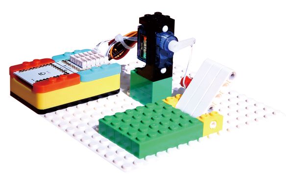
| − | Design a | + | Design a reclining chair of which the angle is adjustable. |
<br> | <br> | ||
Suitable kits: mCookie102, mCookie202, mCookie302, IBC | Suitable kits: mCookie102, mCookie202, mCookie302, IBC | ||
| Line 48: | Line 48: | ||
'''Servo Connector''' | '''Servo Connector''' | ||
<br> | <br> | ||
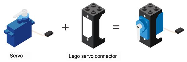
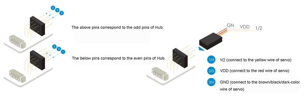
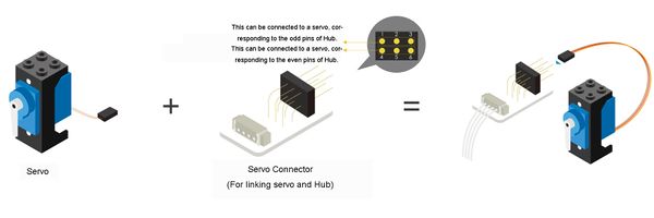
| − | Servo | + | Servo can't be connected to extension module (Hub) directly, it needs the help of servo connector. There are six pins, 3 up, 3 down, of the servo connector, which can be connected to two servos at the same time. |
[[File:anywhere_Servo-Servo Connector.jpg|600px|center]] | [[File:anywhere_Servo-Servo Connector.jpg|600px|center]] | ||
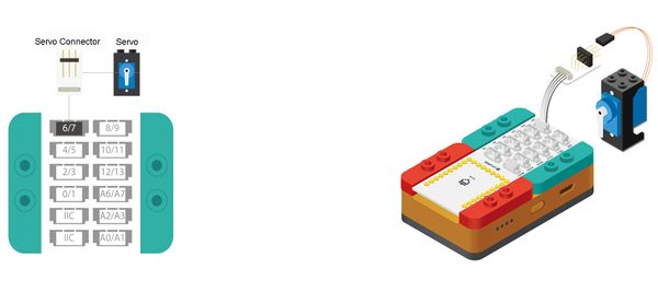
Pay attention to the positive and negative when connecting the servo to the servo connector, and make sure that the GND, VCC, and 1/2 three wires are in right position. The above pins correspond to the odd pins of Hub, and the below correspond to the even pins of Hub. For example, if you want to connect the connector to pin 6/7 of Hub, if you connect the servo to the below pins, the control pin is 6, if connect to the up pins, the control pin is 7. | Pay attention to the positive and negative when connecting the servo to the servo connector, and make sure that the GND, VCC, and 1/2 three wires are in right position. The above pins correspond to the odd pins of Hub, and the below correspond to the even pins of Hub. For example, if you want to connect the connector to pin 6/7 of Hub, if you connect the servo to the below pins, the control pin is 6, if connect to the up pins, the control pin is 7. | ||
| Line 64: | Line 64: | ||
==Programming== | ==Programming== | ||
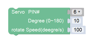
===Required Program Block=== | ===Required Program Block=== | ||
| − | [[ | + | [["Servo" program block]] |
===Programming Thought=== | ===Programming Thought=== | ||
Latest revision as of 19:22, 14 September 2017
|
ContentsOverviewDesign a reclining chair of which the angle is adjustable.
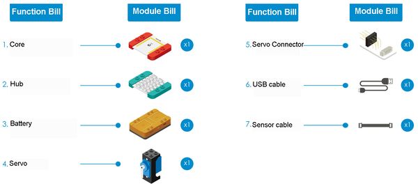
Module BillModule
Other Equipment
Servo
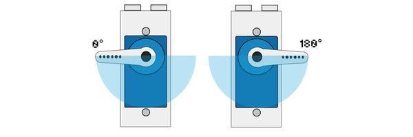
Install the rocker
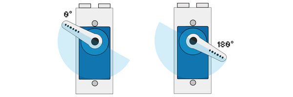
If you find that the rotation range of the rocker doesn’t meet the requirement, as shown on the left diagram, you need to dismount the fixation screws of the rocker with a screwdriver, unplug the rocker, turn it to a certain angle and then install it back to the main axis and rotate it again and observe the rotation range. Servo Connector
Pay attention to the positive and negative when connecting the servo to the servo connector, and make sure that the GND, VCC, and 1/2 three wires are in right position. The above pins correspond to the odd pins of Hub, and the below correspond to the even pins of Hub. For example, if you want to connect the connector to pin 6/7 of Hub, if you connect the servo to the below pins, the control pin is 6, if connect to the up pins, the control pin is 7.
Module Setup
ProgrammingRequired Program BlockProgramming ThoughtWe can control the servo rocker to rotate to any single between 0~180°, just need to make the rocker rotate to an specified angle, and fix the back of the chair on the rocker. Start to Program
Technical Specification
Related CasesQ&A |
