Difference between revisions of "Microduino-Quadcopter Tutorial"
(→Operating Instructions) |
|||
| (8 intermediate revisions by 3 users not shown) | |||
| Line 3: | Line 3: | ||
|- | |- | ||
| | | | ||
| + | {| class="wikitable" style="background-color:#FEF9E7;" | ||
| + | |Check out the <b>[[Quadcopter Kit: Quickstart Guide]]</b>! | ||
| + | |} | ||
==Outline== | ==Outline== | ||
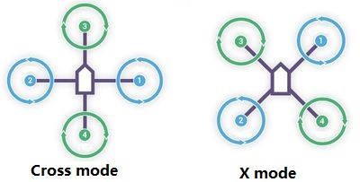
Quadcopter is one kind of aircraft that is equipped with four propellers. Similar to the helicopter, it can finish the action of hover and flight. A traditional helicopter uses a main rotor to generate thrust and a tail rotor to offset the torque from the main rotor, namely, locking the tail. While the quadcopter adopts positive and negative propeller design and therefore, needs no extra structure to lock the tail. Four propellers distribute symmetrically in the shape of a cross. The No. 1 and No. 2 propellers rotate anticlockwise while the No.3 and No.4 rotate<br> clockwise. When the four propellers generate the same thrust, the anti-torque imposed on the body by the two groups offset, balancing in the vertical direction<br> and making sure flight stability. | Quadcopter is one kind of aircraft that is equipped with four propellers. Similar to the helicopter, it can finish the action of hover and flight. A traditional helicopter uses a main rotor to generate thrust and a tail rotor to offset the torque from the main rotor, namely, locking the tail. While the quadcopter adopts positive and negative propeller design and therefore, needs no extra structure to lock the tail. Four propellers distribute symmetrically in the shape of a cross. The No. 1 and No. 2 propellers rotate anticlockwise while the No.3 and No.4 rotate<br> clockwise. When the four propellers generate the same thrust, the anti-torque imposed on the body by the two groups offset, balancing in the vertical direction<br> and making sure flight stability. | ||
| Line 106: | Line 109: | ||
|Module||Number||Function | |Module||Number||Function | ||
|- | |- | ||
| − | |Microduino-CoreRF||1||Core board | + | |[[Microduino-CoreRF]]||1||Core board |
|- | |- | ||
| − | |Microduino-USBTTL ||1||Program download module | + | |[[Microduino-USBTTL]] ||1||Program download module |
|- | |- | ||
| − | |Microduino-Motion ||1||Attitude adjustment | + | |[[Microduino-Motion]] ||1||Attitude adjustment |
|- | |- | ||
| − | |Microduino-QuadCopter||1||Quadcopter driver | + | |[[Microduino-QuadCopter]]||1||Quadcopter driver |
|- | |- | ||
|2.4G Antenna||1|| | |2.4G Antenna||1|| | ||
| Line 132: | Line 135: | ||
|Screwdriver||1|| | |Screwdriver||1|| | ||
|} | |} | ||
| − | [[File: | + | [[File:Quadcopter Material List.jpg|center|1000px]] |
| + | |||
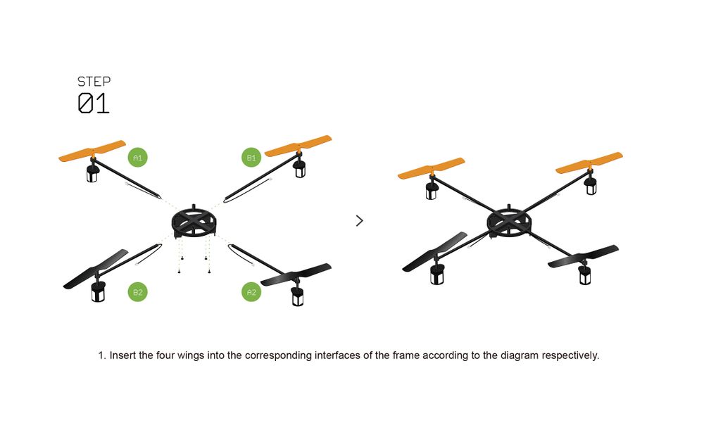
| + | [[File:Quadcopter 1.jpg|center|1000px]] | ||
| + | |||
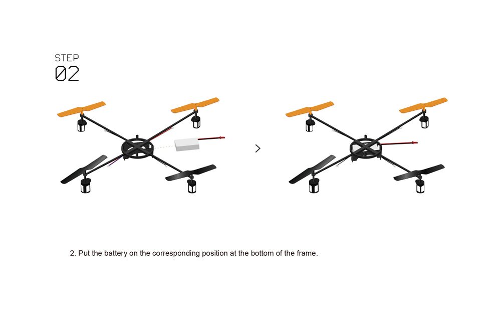
| + | [[File:Quadcopter 2.jpg|center|1000px]] | ||
| + | |||
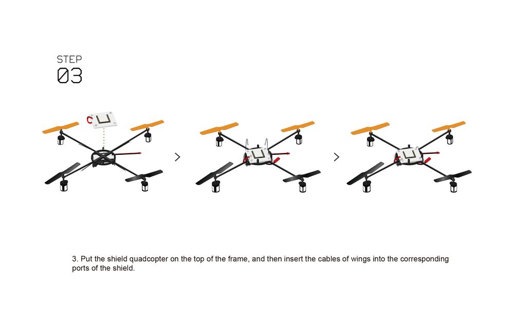
| + | [[File:Quadcopter 3.jpg|center|1000px]] | ||
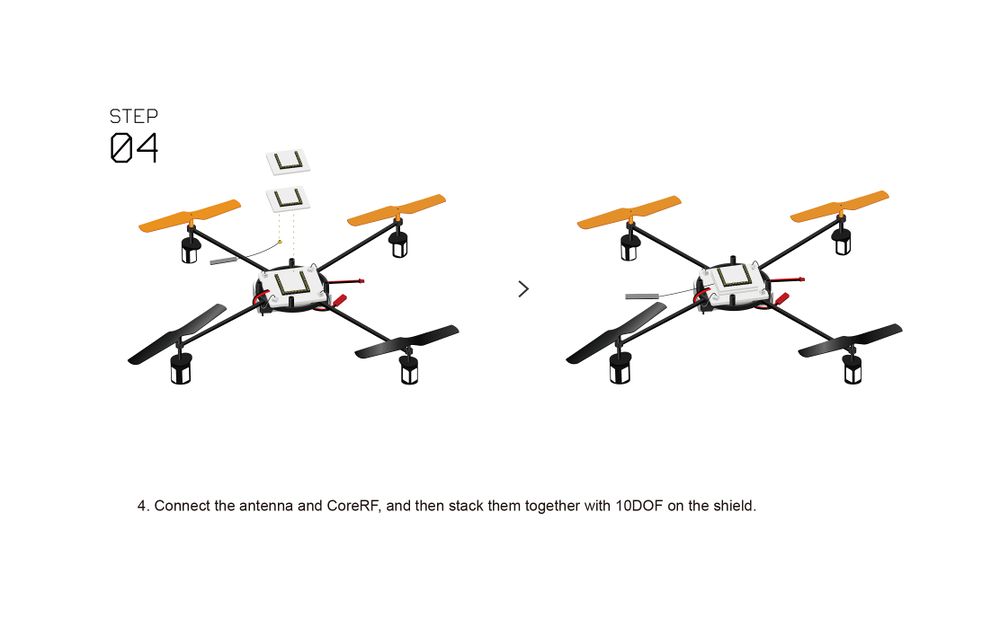
| − | + | [[File:Quadcopter 4.jpg|center|1000px]] | |
| − | [[File: | ||
| − | + | [[File:Quadcopter 5.jpg|center|1000px]] | |
| − | [[File: | ||
| − | + | [[File:Quadcopter 6.jpg|center|1000px]] | |
| − | [[File: | ||
| − | |||
| − | |||
| − | |||
| − | |||
| − | |||
| − | |||
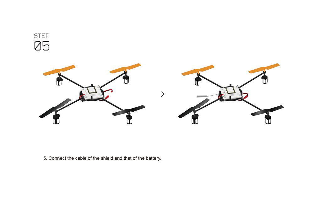
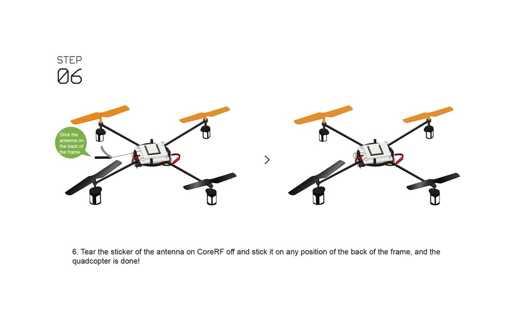
**Please be noted of the electrode of the two wires, which is "red wire connects to red wire" and "black to black". | **Please be noted of the electrode of the two wires, which is "red wire connects to red wire" and "black to black". | ||
**Make sure all wires are connected well in order to prevent accident while flying. | **Make sure all wires are connected well in order to prevent accident while flying. | ||
==Program Download== | ==Program Download== | ||
| − | *The code of the | + | *The code of the quadcopter: '''[https://github.com/wasdpkj/MultiWii_for_Microduino MultiWii_for_Microduino]''' |
==Programming== | ==Programming== | ||
*Stack '''[[Microduino-CoreRF]]''' and '''[[Microduino-USBTTL]]''' together. | *Stack '''[[Microduino-CoreRF]]''' and '''[[Microduino-USBTTL]]''' together. | ||
**Connect the '''[[Microduino-USBTTL]]''' with USB cable and prepare to upload the program. | **Connect the '''[[Microduino-USBTTL]]''' with USB cable and prepare to upload the program. | ||
| − | ** | + | **Note: You'd better upload the programs before stacking all the modules together. |
| − | *Open the Arduino IDE for Microduino environment(Reference of setting | + | *Open the Arduino IDE for Microduino environment(Reference of setting up: '''[[AVR Core:Getting started]]''') |
*Click '''【File】''', confirm '''board card (Microduino-CoreRF)''' selected rightly, and choose the corresponding ''' port number (COMX)'''. | *Click '''【File】''', confirm '''board card (Microduino-CoreRF)''' selected rightly, and choose the corresponding ''' port number (COMX)'''. | ||
| − | *Click '''【File】'''->'''【Open】''', browse to the project program address, and click ''' | + | *Click '''【File】'''->'''【Open】''', browse to the project program address, and click '''"MultiWii_for_CoreRF.ino"''' to open it. |
*After confirming all these are right, click '''"→"''' to download the program to the development board. | *After confirming all these are right, click '''"→"''' to download the program to the development board. | ||
*Microduino-USBTTL download module is used when download programs and debug serial ports and correct the quadcopter, and you can not stack it at other time. | *Microduino-USBTTL download module is used when download programs and debug serial ports and correct the quadcopter, and you can not stack it at other time. | ||
| Line 179: | Line 179: | ||
*Close the automatic correction function. | *Close the automatic correction function. | ||
**You must configure manually after close the automatic correction. | **You must configure manually after close the automatic correction. | ||
| − | **Open the '''config.h''' file in the quadcopter code, and note all the following | + | **Open the '''config.h''' file in the quadcopter code, and note all the following code: |
***//#define MICRODUINO_AUTO_CALIBRATING // configuration of the free host computer, autocorrection of the gyroscope on starting up | ***//#define MICRODUINO_AUTO_CALIBRATING // configuration of the free host computer, autocorrection of the gyroscope on starting up | ||
***//#define MICRODUINO_AUTO_ANGLE //configuration of the free host computer, and open of the configuration of the self-stabilization function | ***//#define MICRODUINO_AUTO_ANGLE //configuration of the free host computer, and open of the configuration of the self-stabilization function | ||
| Line 185: | Line 185: | ||
*Connect the quadcopter to the computer. | *Connect the quadcopter to the computer. | ||
| − | ** | + | **Connect the computer with the '''[[Microduino-USBTTL]]''' in the quadcopter with USB cable. |
**Confirm '''[[Microduino-CoreRF]]''' and '''[[Microduino-10DOF]]''' have been stacked normally. | **Confirm '''[[Microduino-CoreRF]]''' and '''[[Microduino-10DOF]]''' have been stacked normally. | ||
| Line 208: | Line 208: | ||
*Accelerometer correction. | *Accelerometer correction. | ||
**Click '''CALIB_ACC''' button. | **Click '''CALIB_ACC''' button. | ||
| − | ** | + | **About during 5s, just wait for the data smooth. |
**Click WRITE to write the values into the flight control, to complete the correction. | **Click WRITE to write the values into the flight control, to complete the correction. | ||
| Line 216: | Line 216: | ||
*Debugging with sensor values. | *Debugging with sensor values. | ||
| − | **Lean the body of the fuselage to the right( lift the left side | + | **Lean the body of the fuselage to the right( lift the left side up): |
***The values of ACC_ROLL and GYRO_ROLL increase. | ***The values of ACC_ROLL and GYRO_ROLL increase. | ||
***The value of ACC_Z decreases. | ***The value of ACC_Z decreases. | ||
| − | **Make the fuselage lean forward(lift the tail | + | **Make the fuselage lean forward(lift the tail up): |
***The values of ACC_PITCH and GYRO_PITCH increase. | ***The values of ACC_PITCH and GYRO_PITCH increase. | ||
***The value of ACC_Z decreases. | ***The value of ACC_Z decreases. | ||
| − | **Make the fuselage rotate in clockwise | + | **Make the fuselage rotate in clockwise direction(yaw): |
***The value of CYRO_YAW increases. | ***The value of CYRO_YAW increases. | ||
| − | **The fuselage keeps | + | **The fuselage keeps level: |
***The value of ACC_Z is positive. | ***The value of ACC_Z is positive. | ||
| − | *After the correction, we recommend that download '''[[Microduino-USBTTL]]] module to reduce the weight of the quadcopter. | + | *After the correction, we recommend that download '''[[Microduino-USBTTL]]] module to reduce the weight of the quadcopter. |
| − | |||
===Joypad Remote Controller Guide=== | ===Joypad Remote Controller Guide=== | ||
| − | *For setup process, you can refer to the following | + | *For setup process, you can refer to the following page: '''[[Microduino-Joypad_Getting_start|Microduino Joypad Getting Started Guide of the Usage of Joypad]]''' |
*'''Configuration of Joypad communication mode'''* | *'''Configuration of Joypad communication mode'''* | ||
| − | *You can refer to the following page for mode | + | *You can refer to the following page for mode configuration: '''[[Microduino-Joypad_Getting_start#Communication_Model|For Quadcopter]]''' |
| − | **When we use '''[[Microduino-CoreRF]]''' as the '''communication''', Joypad | + | **When we use '''[[Microduino-CoreRF]]''' as the '''communication''', Joypad pick '''"Quadro"''' accordingly. |
*'''Instruction of Joypad Battery'''* | *'''Instruction of Joypad Battery'''* | ||
| − | *Special attention should be paid to the battery instruction:'''[ | + | *Special attention should be paid to the battery instruction:'''[[Microduino-Joypad_Getting_start#Step-3_Battery_powered|Instruction for Battery]]''' |
===Guide of Joypad Unlocking/Locking=== | ===Guide of Joypad Unlocking/Locking=== | ||
====Traditional Method==== | ====Traditional Method==== | ||
| − | *Confirm the corresponding switch state of | + | *Confirm the corresponding switch state of Joypad: |
| − | **Whether locked or unlocked, you need confirm the state of Joypad switch is as | + | **Whether locked or unlocked, you need confirm the state of Joypad switch is as following: |
**Dial Joypad''' top left shift switch ''' down(the throttle lock is open). | **Dial Joypad''' top left shift switch ''' down(the throttle lock is open). | ||
**Dial Joypad''' top right shift switch''' up(the rocker amplitude is the largest). | **Dial Joypad''' top right shift switch''' up(the rocker amplitude is the largest). | ||
| − | *Initialization of the | + | *Initialization of the quadcopter: |
**Place the quadcopter on the horizontal ground and open the power supply. | **Place the quadcopter on the horizontal ground and open the power supply. | ||
**Wait the indicator light on the quadcopter stop flashing. | **Wait the indicator light on the quadcopter stop flashing. | ||
| − | * | + | *Unlock: |
**Turn the '''left stick''' to '''the rightest''' from the midst, and wait for about 2S. | **Turn the '''left stick''' to '''the rightest''' from the midst, and wait for about 2S. | ||
**If the indicator light '''keep lighting''', it is '''unlocked'''. Otherwise, turn the '''left stick''' to the midst, and operate this step again. | **If the indicator light '''keep lighting''', it is '''unlocked'''. Otherwise, turn the '''left stick''' to the midst, and operate this step again. | ||
| − | **If you | + | **If you can't unlock after many times of attempt, you need to reset the core of the quadcopter and then try again. |
| − | * | + | *Lock: |
**Under the situation that it is '''unlocked''', and the quadcopter stay '''still''' | **Under the situation that it is '''unlocked''', and the quadcopter stay '''still''' | ||
**Turn the '''left stick''' to the '''leftest''' from the midst and wait for about 2S. | **Turn the '''left stick''' to the '''leftest''' from the midst and wait for about 2S. | ||
| Line 266: | Line 265: | ||
***#define MICRODUINO_AUTO_ARM //free host computer configuration, and AUX1 channel a key to unlock. The traditional unlocking method is invalid at this time. | ***#define MICRODUINO_AUTO_ARM //free host computer configuration, and AUX1 channel a key to unlock. The traditional unlocking method is invalid at this time. | ||
| − | *Confirm the state of the corresponding switch of | + | *Confirm the state of the corresponding switch of Joypad: |
| − | **Whether locking of unlocking, you need to make sure the state of Joypad switch is as | + | **Whether locking of unlocking, you need to make sure the state of Joypad switch is as following: |
**Dial the Joypad '''top left shift switch''' down(the throttle lock is open). | **Dial the Joypad '''top left shift switch''' down(the throttle lock is open). | ||
**Dial the Joupad '''top sight shift switch''' up(the rocker amplitude is the largest). | **Dial the Joupad '''top sight shift switch''' up(the rocker amplitude is the largest). | ||
| − | **The | + | **The quadcopter's AUX1 channel is low(key1 button control). |
| − | *Quacopter | + | *Quacopter initialization: |
**Pu the quadcopter level on the ground and open the power supply. | **Pu the quadcopter level on the ground and open the power supply. | ||
**Wait the indicator light on the quadcopter stop blinking(if it is blinking all the time, please check whether the AUX1 channel is low). | **Wait the indicator light on the quadcopter stop blinking(if it is blinking all the time, please check whether the AUX1 channel is low). | ||
| − | * | + | *Unlock: |
**Press the '''key1''' of Joypad down, and put the '''AUX1 channel''' high. | **Press the '''key1''' of Joypad down, and put the '''AUX1 channel''' high. | ||
**If the indicator light '''keep lighting''', it is '''unlocked'''. | **If the indicator light '''keep lighting''', it is '''unlocked'''. | ||
| − | **If it | + | **If it can't be unlocked after many times of attempt, you should reset the core of the quadcopter and try again. |
*Lock: | *Lock: | ||
| Line 288: | Line 287: | ||
===Control Guide of Joypad=== | ===Control Guide of Joypad=== | ||
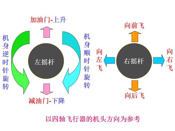
| − | *'''Be sure to read''' the following letters, to guarantee your '''security''' | + | *'''Be sure to read''' the following letters, to guarantee your '''security''': |
**The quadcopter is unlocked, and put on the open area. | **The quadcopter is unlocked, and put on the open area. | ||
**Make sure your Joypad has enough power. | **Make sure your Joypad has enough power. | ||
| − | **Make sure you | + | **Make sure you won't be in the quadcopter unlocking state, and close Joypad at first. |
**The direction of the nose of quadcopter is that of the orange oar. | **The direction of the nose of quadcopter is that of the orange oar. | ||
**Before remove the lock of the throttle, make sure that the throttle of Joypad is closed(adjust the left rocker to the lowest). | **Before remove the lock of the throttle, make sure that the throttle of Joypad is closed(adjust the left rocker to the lowest). | ||
| Line 300: | Line 299: | ||
[[File:Microduino_QuadCopter_Remote6.jpg|600px|center]] | [[File:Microduino_QuadCopter_Remote6.jpg|600px|center]] | ||
| − | *Next, you can prepare for the | + | *Next, you can prepare for the flight: |
**Dial the Joypad '''top left switch''' up(close the throttle lock). | **Dial the Joypad '''top left switch''' up(close the throttle lock). | ||
| Line 318: | Line 317: | ||
Although the above contents list a lot of problems that should be paid attention to, they need to be summarized here. | Although the above contents list a lot of problems that should be paid attention to, they need to be summarized here. | ||
*For installation | *For installation | ||
| − | **The four propellers of the quadcopter are installed in order. If you install wrongly, it is likely to lead to that the aircraft | + | **The four propellers of the quadcopter are installed in order. If you install wrongly, it is likely to lead to that the aircraft can't fly. |
**The positive and negative of the lithium battery. The red line is for the positive pole, and the black line is for the negative pole. The circuit is easy to burn out once connect wrongly. Especially when supply power to Microduino-Joypad, because there is no design for avoiding plugging inversely, it should be noted. | **The positive and negative of the lithium battery. The red line is for the positive pole, and the black line is for the negative pole. The circuit is easy to burn out once connect wrongly. Especially when supply power to Microduino-Joypad, because there is no design for avoiding plugging inversely, it should be noted. | ||
*For adjustment of the parameters | *For adjustment of the parameters | ||
| − | **Refer to the content of section 4 to adjust the PID parameter of the aircraft and the flight mode. And | + | **Refer to the content of section 4 to adjust the PID parameter of the aircraft and the flight mode. And you'd better modify them on the basis of the recommended configuration. If you want to manually modify the PID parameters, you’d better modify one parameter at one time, otherwise it is difficult to see which parameters work. |
*For debugging | *For debugging | ||
**You must correct the controller(Microduino-Joypad)and aircraft, or it is easy to cause the aircraft flying unstably. | **You must correct the controller(Microduino-Joypad)and aircraft, or it is easy to cause the aircraft flying unstably. | ||
| Line 330: | Line 329: | ||
*For charging/dry battery | *For charging/dry battery | ||
**The aircraft plate has the function of charge the battery of the aircraft directly, so you only need to plug the USB cable to supply power to the baseboard directly. | **The aircraft plate has the function of charge the battery of the aircraft directly, so you only need to plug the USB cable to supply power to the baseboard directly. | ||
| − | **Joypad adopts dry battery to supply power, and you should dial the battery selection switch to Dry bat. Set up the dry battery, and on supplying power to joypad with USB cable, '''pull out at once'''(It | + | **Joypad adopts dry battery to supply power, and you should dial the battery selection switch to Dry bat. Set up the dry battery, and on supplying power to joypad with USB cable, '''pull out at once'''(It can't be charged with USB cable for a long time after installing the dry battery), then you can successfully activate the dry battery to supply power. |
If other problems appear, please put forward in the discussion part. | If other problems appear, please put forward in the discussion part. | ||
|} | |} | ||
Latest revision as of 22:36, 4 October 2018
| Language: | English • 中文 |
|---|
Contents[hide]OutlineQuadcopter is one kind of aircraft that is equipped with four propellers. Similar to the helicopter, it can finish the action of hover and flight. A traditional helicopter uses a main rotor to generate thrust and a tail rotor to offset the torque from the main rotor, namely, locking the tail. While the quadcopter adopts positive and negative propeller design and therefore, needs no extra structure to lock the tail. Four propellers distribute symmetrically in the shape of a cross. The No. 1 and No. 2 propellers rotate anticlockwise while the No.3 and No.4 rotate | ||||||||||||||||||||||||||||||||||||
| According to the user-defined fore and aft direction of the aircraft, the quadcopter can be divided into the cross mode and X mode. The cross mode means that the fore and aft direction points to a certain propeller and the X mode refers to that the fore and aft direction points to the middle of two propellers.
| ||||||||||||||||||||||||||||||||||||
For most aircraft adopting X mode, the X mode is harder to control but more flexible.
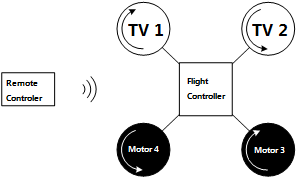
PrincipleSystem StructureAs the picture shows, the Quadopcter consists of a remote controller, a flight controller and four motors. And for the flight controller includes a microcontroller, a remote control signal receiving module, a motor driving module and sensor modules (A gyroscope, an accelerator, an electronic compass and a GPS module).
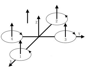
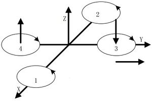
Flying PrincipleVertical MotionVertical motion includes rising or falling vertically. As the text mentioned previously, the quadcopter can keep balance horizontally by four motors maintaining the same rotation rate. As you can see from picture 2.2.1, if the four motors increase to the same speed, the generated thrust will be large enough to overcome the quadcopter weight and rise, and vice versa. Under the condition of no surrounding interruption, the four motors can generate enough thrust to overcome the weight and therefore, the quadcopter can suspend in the air.
| ||||||||||||||||||||||||||||||||||||
| The quadcopter can fly steadily in the vertical direction as long as the four motors maintain the same speed.
Front & Lateral MotionThe motor 1 is the head of the aircraft and the motor 2 is the rear.
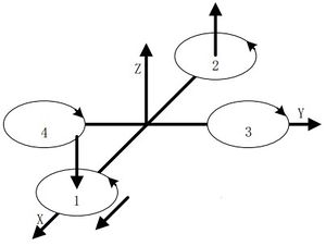
Yawing MotionThe three kinds of motion mentioned above all happen in the directions of the three axes. Next, we'll introduce the motion around the three axes. | ||||||||||||||||||||||||||||||||||||
| Yawing motion is the rotation in the horizontal direction, namely rotation around the Z-axis.
During the rotation, it will form an anti-torque opposite to the rotation due to air resistance. Yawing rotation is realized by using the reverse torque. When the aircraft suspends, the speed of the four motors is the same, which can offset torque in both horizontal and vertical direction, and achieve balance. When the speed of the four motors is different, unbalanced anti-torque will cause horizontal rotation and the aircraft will deviate from the route. As the picture shows, by increasing the speed of the motor 1 and 2, and decreasing that of the motor 3 and 4, the clockwise anti-torque generated by the motor 1 and 2 will be larger than the counter clockwise anti-torque generated by the motor 3 and 4, causing clockwise rotation of the aircraft horizontally and generating no vertical displacement when there is no change in the thrust upside. Pitch and Roll MotionPitch motion refers to the rotation in the Y-axis direction while the roll motion refers to the rotation in the X-axis direction. | ||||||||||||||||||||||||||||||||||||
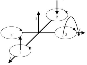
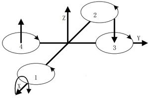
| As the picture shows, by increasing the speed of the motor 1 and decreasing that of the motor 2, and keeping the same of the variable quantity as well as the speed of the motor 3 and 4: The thrust of the head is larger than that of the rear. The unbalanced torque makes the body rise. Similarly, the roll motion is realized by reducing the speed of the motor 1 and increasing that of the motor 2, generating a torque forward. | ||||||||||||||||||||||||||||||||||||
The principle of the roll and pitch motion is the same due to symmetry in the middle. By keeping the speed of the motor 1 and 2 unchanged, and changing the speed of motor 3 and 4, it'll generate unbalanced torque and make the aircraft rotate around the X-axis direction.
Control ProcedureThe remote controller sends out control command, such as take-off or flying left. The control signal is received wirelessly.
| ||||||||||||||||||||||||||||||||||||
| Since the four-motor combination control can only reach to six directions, which is an under actuated system. So here we must have a flight controller to control the whole system. | ||||||||||||||||||||||||||||||||||||
| In the flight controllers, sensors such as gyroscope and accelerator are dispensable. Micro controller can calculate data from the two sensors, get the current aircraft's attitude and then adjust the rotation rate with algorithms such PID to keep the stability. Sure you can add an electronic compass to get the direction or a GPS module to get the geographic location. Simply speaking, the quadcopter is system with two closed-loops to control---the large loop gets input volume from the remote receiving device and the small loop acquires input volume from the attitude sensor. | ||||||||||||||||||||||||||||||||||||
| Generally speaking, the quadcopter kit includes an aircraft and a remote controller, the two of which controls instructions through the CoreRF transmission. | ||||||||||||||||||||||||||||||||||||
| The quadcopter is composed of a frame, Microduino-CoreRF , Microduino-Motion and other modules. For Microduino-motion, it integrates a three-axis gyroscope + a three-axis accelerator(MPU6040), a magnetic field intensity sensor(HMC5883L) and a digital pressure sensor(BMP180), and have communication through IIC. | ||||||||||||||||||||||||||||||||||||
MPU6050 is the most important attitude sensor with a three-axis accelerator and a three-axis gyroscope integrated inside, which not only offsets adjustment errors for the combination of a three-axis accelerator and a three-axis gyroscope, and also has a built-in low pass filter.
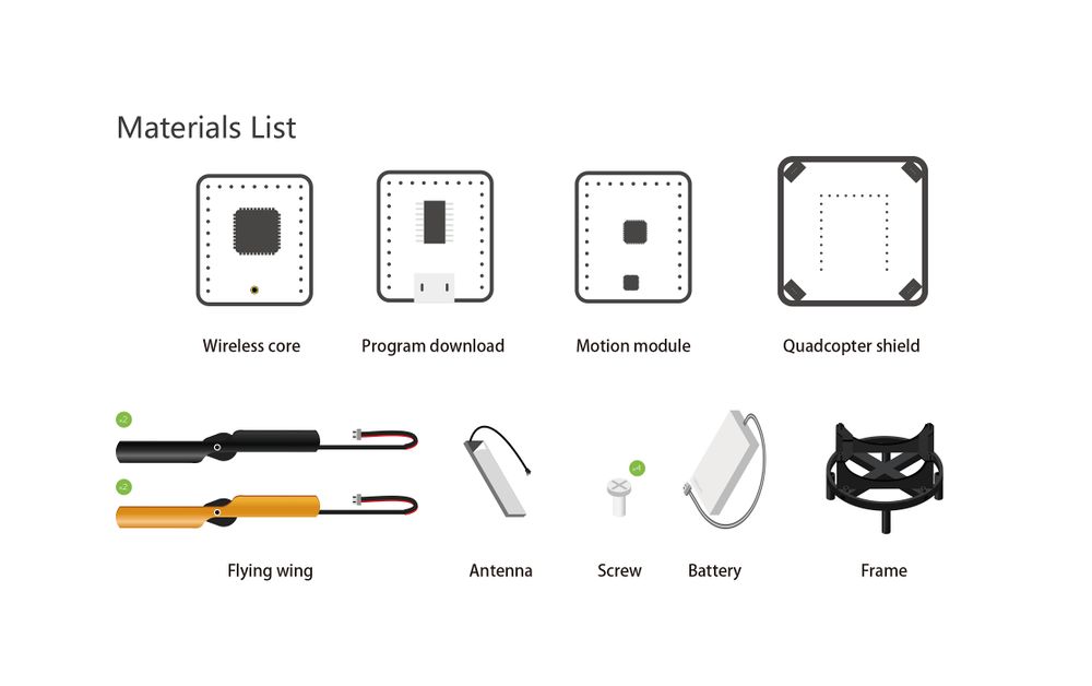
Buildup and DebuggingBill of Materials
Program Download
Programming
Operating InstructionCorrection Guide of QaudcopterAutocorrection(recommended)
Manual Correction
Joypad Remote Controller Guide
Guide of Joypad Unlocking/LockingTraditional Method
A Key Method
Control Guide of Joypad
Program DescriptionAttentionAlthough the above contents list a lot of problems that should be paid attention to, they need to be summarized here.
If other problems appear, please put forward in the discussion part. |
