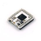
This quick start guide is intended to get the reader started with the Quadcopter (w/ Joypad) kit.
This guide will cover the following:
- Setting up the programming software.
- Programming and assembling the Quadcopter.
- Programming and assembling the Joypad.
- Joypad usage and basic control of the Quadcopter.
Software Setup
Please follow the guide to ensure your software is correctly setup. The software is required to program both the Quadcopter and Joypad.
Download the latest software for your operating system and follow the getting started guides:
Programming the Quadcopter
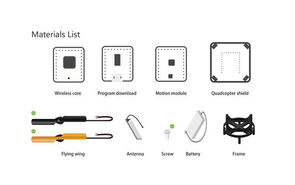
In the Quadcopter box should be two modules:
- Microduino CoreRF - the brains of the Quadcopter. A tiny CPU with RF communication capabilities.
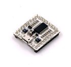
- Microduino USBTTL - programmer which writes the program from your computer to the Microduino CoreRF module.
The Microduino CoreRF must be programmed with the "Quadcopter" code using the Microduino USBTTLC.
- Download the code for the Quadcopter: File:MultiWii for CoreRF.zip
- Extract the .zip folder somewhere. Ensure, you know where the folder is as you will need to navigate to it.
- Open the Arduino for Microduino software (follow the #Software Setup section if you have not yet).
- In the software, go to File > Open... and navigate to the extracted folder. Select and open the MultiWii_for_CoreRF.ino file. The code should now appear in the software.
- Configure the software to program the CoreRF module:
- Tools > Board and select Microduino/mCookie-device.
- Tools > Processor and select Microduino/mCookie-Core RF (127rfa1)
- Stack the Microduino CoreRF module onto the Microduino USBTTL module. Plug one end of the MicroUSB into the Microduino USBTTL and the other end to the computer.
- Go back to the software and select the port:
- Tools > Port and select what is usually selectable. (Note: if on Mac, the port is NOT the Bluetooth ones.)
- Now upload the program by click on the Right Arrow icon on the top left of the software. This is the upload button. Wait for the code to compile and then uploading will proceed. The software will inform once uploading is done on the bottom left.
- Disconnect the MicroUSB cable from the Microduino USBTTL. Separate (unstack) the two modules (CoreRF and USBTTL).
- Note: Please be careful when separating the boards as the pins can be damaged. It is recommended to use a flat object to slowly lever one side a little, then slowly lever the other side a little, repeating until the modules separate easily.
- Place the Microduino USBTTL module aside. As it will be used to program the Joypad later.
Quadcopter Assembly
Other Equipment
| Component |
Number |
Function
|
| USB Cable |
1 |
|
| Frame |
1 |
|
| Battery |
1 |
Power supply
|
| Screw |
8 |
|
| Screwdriver |
1 |
|
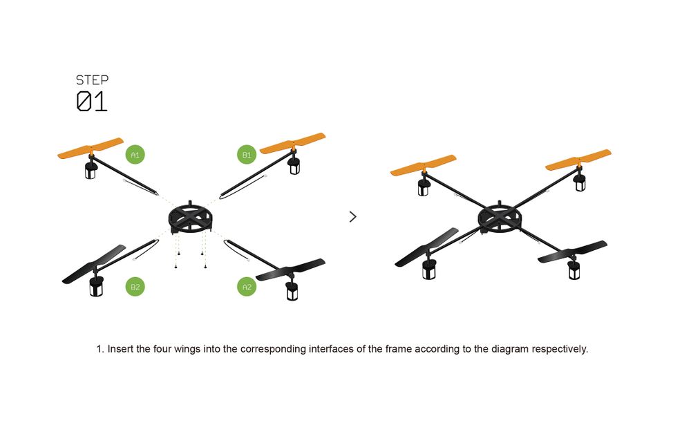
| IMPORTANT: Ensure that the correct wing is inserted into the correct position!
|
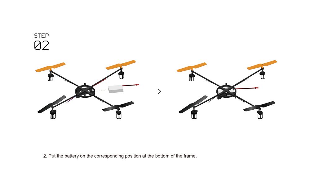
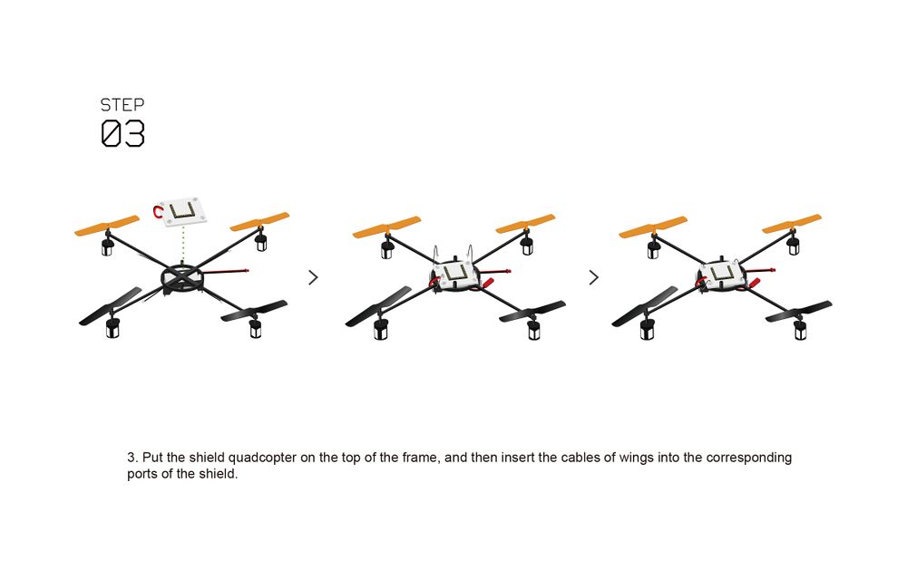
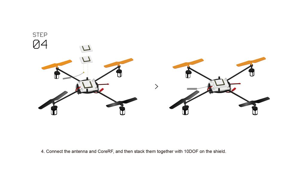
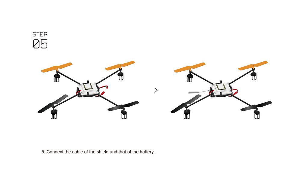
| Note: 10DOF is also known as the Motion module.
|
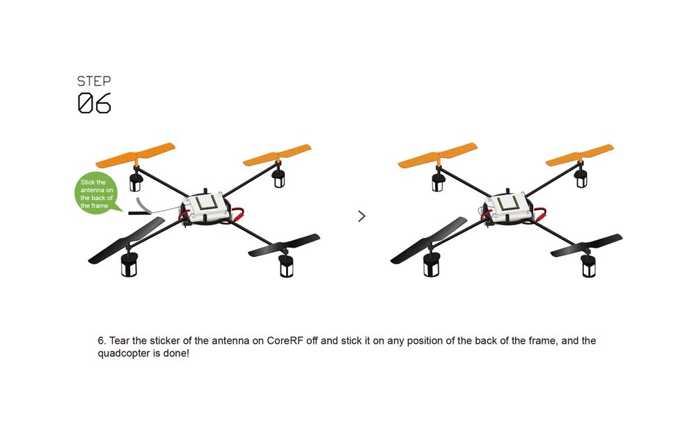
Programming the Joypad
In the Joypad box should be a Microduino CoreRF:
- Microduino CoreRF - the brains of the Joypad. A tiny CPU with RF communication capabilities.
The Microduino CoreRF must be programmed with the "Joypad" code using the Microduino USBTTL. Note: You'll be using the same Microduino USBTTL from the Quadcopter box.
- Download the code for the Joypad: File:Joypad RC.zip
- Extract the .zip folder somewhere. Ensure, you know where the folder is as you will need to navigate to it.
- Open the Arduino for Microduino software (follow the #Software Setup section if you have not yet).
- In the software, go to File > Open... and navigate to the extracted folder. Select and open the Joypad_RC.ino file. The code should now appear in the software.
- Configure the software to program the CoreRF module:
- Tools > Board and select Microduino/mCookie-device.
- Tools > Processor and select Microduino/mCookie-Core RF (127rfa1)
- Stack the Microduino CoreRF module onto the Microduino USBTTL module. Plug one end of the MicroUSB into the Microduino USBTTL and the other end to the computer.
- Go back to the software and select the port:
- Tools > Port and select what is usually selectable. (Note: if on Mac, the port is NOT the Bluetooth ones.)
- Now upload the program by click on the Right Arrow icon on the top left of the software. This is the upload button. Wait for the code to compile and then uploading will proceed. The software will inform once uploading is done on the bottom left.
- Disconnect the MicroUSB cable from the Microduino USBTTL.
Assembling the Joypad
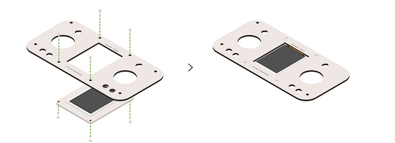
Step 1:
- Place the TFT (screen) into the face panel of the Joypad. Note the orientation of the screen. Notice the yellow/orange ribbon cable.
- Use 4 screws to attach the screen to the face panel.
|

| Step 2: Connect the TFT cable to the back of the TFT (screen). As shown.
|
| Note: Newer versions of the Joypad contains a pre-installed battery. Use the USB Charging port to charge the pre-installed battery.
|
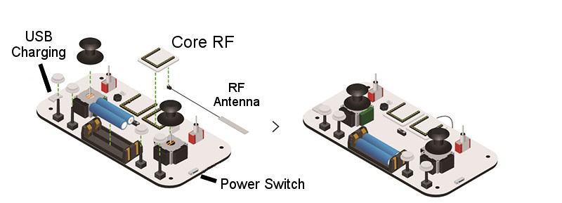
Step 3: Place the following components into their appropriate locations as shown:
- 2 Joystick caps
- 4 White button caps.
- Connect the RF Antenna to the CoreRF.
- Socket the CoreRF module into the Joypad as shown.
| Note: Make a mental note of the locations of the USB Charging port and Power Switch.
|
|
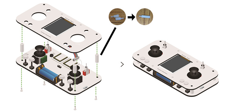
Step 4:
- Double check all the components (2 Joystick caps, 4 White button caps, and CoreRF w/ attached antenna) from Step 3 are in place.
- Connect the other end of the TFT cable to the Joypad as shown.
- With the 8 included hex screws, create 4 large hex screws. An example is shown in the image.
- Attach the 4 large hex screws to the bottom part of the Joypad using 4 screws.
|
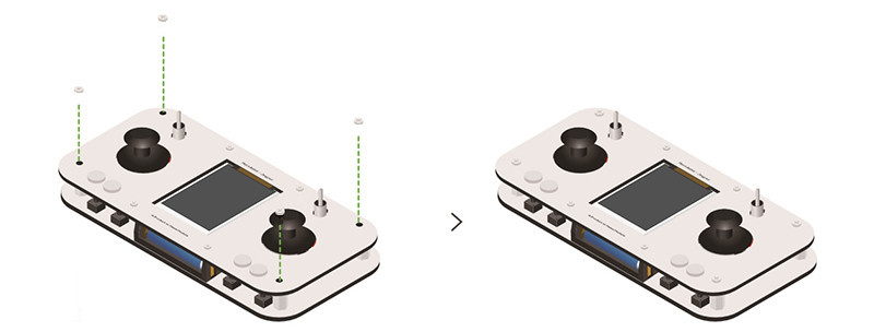
Step 5:
- Attach the front of the Joypad (with screen) to the large hex screws using 4 nuts. As shown.
|
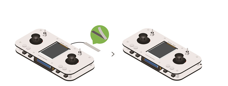
Step 6:
- Remove the sticker from the RF Atntenna and affix it to the back of the Joypad. Assembly of Joypad is complete!
|
Joypad Usage
Layout
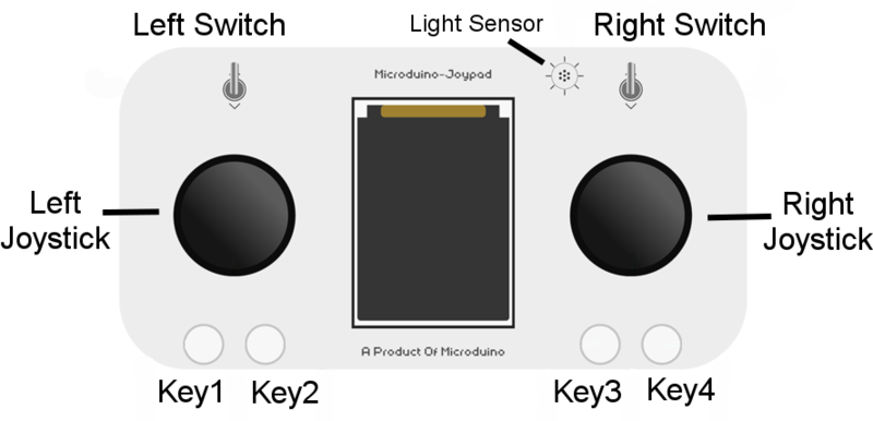
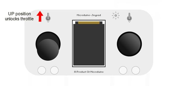
- Left Switch - Down position locks the throttle. Up position unlocks the throttle.
- Right Switch - Down position limits the range of Roll, Pitch and Yaw. Up position unlocks the full range.
- Left Joystick - Control the throttle and rotation of the Quadcopter. Down position, the throttle is off. Up position, the throttle is fully on. Left/Right position will cause the Quadcopter to rotate.
- Right Joystick - Control the position of the Quadcopter.
- Key1 - Used to configure the Joypad. Can also be used for Quadcopter pairing. Also AUX1.
- Key2/3/4 - Used to configure the Joypad. Also AUX2/3/4 correspondingly.
- Light Sensor - Unused.
Configuration
- Switch on the Joypad with the switch on the right side.
- Press Key1 within 2 seconds to enter Configuration mode.
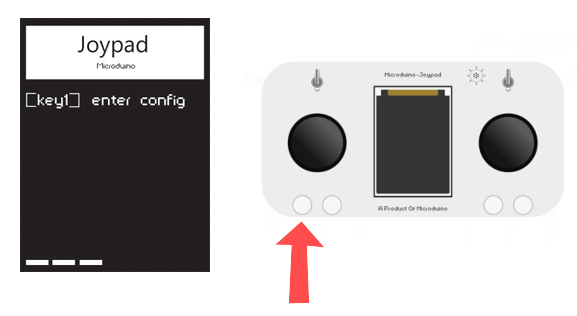
- Navigate the menu with the following keys
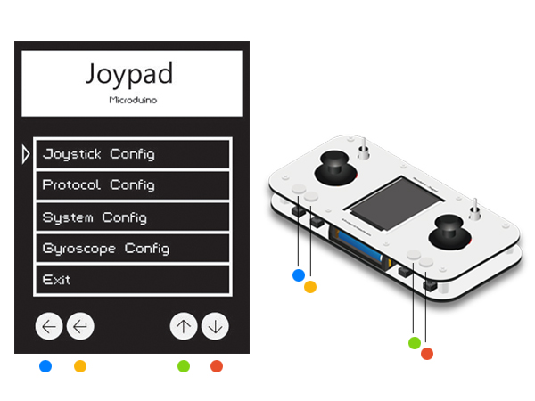
- key1 - back
- key2 - confirm
- key3 - up
- key4 - down
Joystick Calibration
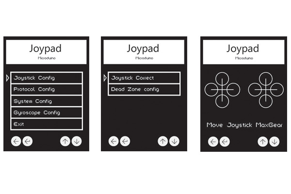
- Enter the Joystick Config menu. Use key2 for enter.
- Then enter to the Joystick Correct. to start calibrating the Joysticks.
- You'll notice two + signs. Rotate the left Joystick in a few circles. The + will have large circle on the ends. Do the same with the right Joystick. As shown. (Use key2 to confirm.)
Mode Selection (for Quadcopter)
- Navigate the menus to Protocol Config, then to Mode. Select Quadro. (Use key2 to confirm.)
- Navigate back up, to find the Quadrotor Channel, set it to 11. (Use key2 to confirm.)
- Navigate back up to the main menu, then select Exit. Joypad configuration s now complete.
First Flight
| IMPORANT: Please have your first flight in an open space. It may take several flights before getting a "feel" of the Quadcopter. It is important to wear safety equipment such as safety goggles.
|
| IMPORANT: It is important to turn on the Quadcopter sitting on a flat surface since the gyroscope calibrates on start up. Therefore, if turning the Quadcopter on an uneven surface or while holding it in your hand will result in a mis-calibrated gyroscope.
|
- Place your Quadcopter on a flat surface. Turn on the Quadcopter using the switch. A blue LED will start blinking. This means the Quadcopter is ready to be paired with.
- There is a special procedure to pair the Joystick with the Quadcopter. On the Joypad set the following:
- TOP LEFT switch to the DOWN position.
- TOP RIGHT switch to the UP position.
- LEFT JOYSTICK to the DOWN position.
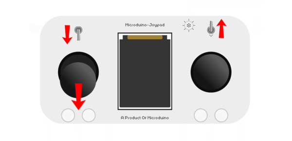
- Turn on the Joypad, wait for the Joypad to fully start up. You should see a screen wtih Roll, Pitch, Yaw, etc.
- Once the Joypad is on, ensure the switches and joystick is set as shown on the image above.
- To begin the pairing procedure bring the Left Joystick from the DOWN position to the RIGHT position in a quarter-circle movement as shown below.
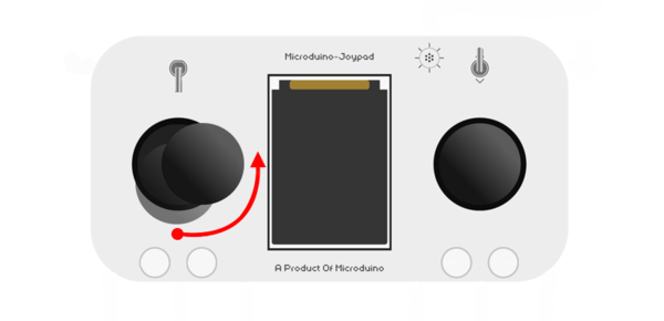
- If pairing is successfully, the blinking blue LED on the Quadcopter will turn SOLID blue (this indicates the Quadcopter and Joypad are paired).
| Note: If pairing is not successful. You will have to perform the Joystick movement again (or several times) until the blue LED is SOLID blue on the Quadcopter.
|
| Note: Pairing must be re-established whenever the connection is disconnected, such as when Quadcopter is turn off or the Joypad is turned off.
|
- Bring the left Joystick back to the DOWN position. The Left Joystick controls the throttle of the Quadcopter. The Right Joystick control the position of the Quadcopter.
- Flip the top left switch to the UP position. This will unlock the throttle. Please prepare for your first flight!
| IMPORANT: Please have your first flight in an open space. It may take several flights before getting a "feel" of the Quadcopter. It is important to wear safety equipment such as safety goggles.
|
| IMPORANT: If you need to abandon the flight. Turn off the throttle (Left Joystick to the DOWN position). This will cut off the power to the motors and cause the Quadcopter to forcibly land.
|
- SLOWLY bring the Left Joystick upwards. The Quadcopter's motors should start up and eventually the Quadcopter start flying. Use the Right Joystick to controls the positioning.
Congratulations on surviving your first flight!
| IMPORANT: When powering off your Quadcopter and Joypad. It is important to turn off the Quadcopter FIRST, then the Joypad. Turning off the Joypad first can cause to the Quadcopter to develop a mind of its own and become self-aware.
|
See Also


