|
|
| Line 35: |
Line 35: |
| | |[[Microduino-Duo-v]] ||1||Reduce the overall height | | |[[Microduino-Duo-v]] ||1||Reduce the overall height |
| | |- | | |- |
| − | |[[Microduino-Module Sensor Hub]] ||1||Sensor linking | + | |[[Microduino-Sensor Hub]] ||1||Sensor linking |
| | |- | | |- |
| | |[[Microduino-Sound]] ||1||Collect voice | | |[[Microduino-Sound]] ||1||Collect voice |
| Line 43: |
Line 43: |
| | |[[Microduino-Buzzer]]||1||Buzzer, alarm | | |[[Microduino-Buzzer]]||1||Buzzer, alarm |
| | |- | | |- |
| − | |[[Microduino-Color led]] ||1||Alarm and flash | + | |[[Microduino-Color LED]] ||1||Alarm and flash |
| | |} | | |} |
| | | | |
Outline
- Project:Microduino open source voice decibel detector
- Objective:Monitor noise, and it will give an alarm when the threshold is surpassed.
- Difficulty:Medium
- Time-consuming:1 hour
- Maker:ray
- Introduction:
- In this tutorial we will use Microduino product module to quickly set up a noise detector.
- It can detect the constant noise and give an alarm with buzzer and LED lights.
- The noise decibel value will be displayed on the OLED screen.
Bill of Material
|
|
| Module |
Number |
Function
|
| Micro-USB cable |
1 |
Program download, and power supply
|
| Wooden casing suite |
1 |
The appearance, and fixation
|
| M2 screw |
15 |
Structure fixation
|
| M2 nut |
15 |
Structure fixation
|
| Screwdriver |
1 |
Tool
|
|
Principle of the Experiment
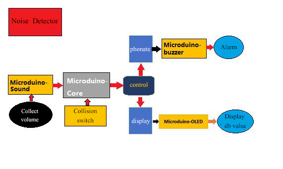
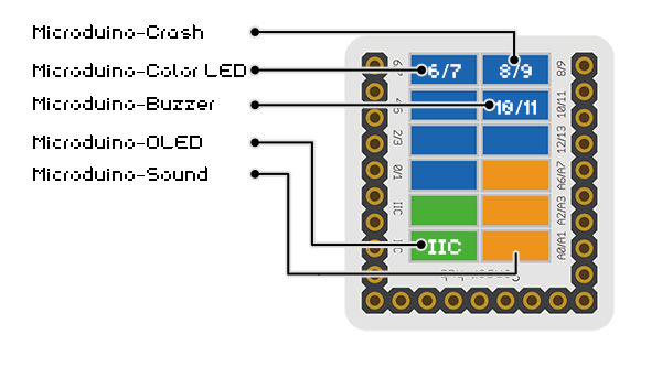
- Collect voice in the environment through mCookie-Sensor MIC microphone sensor.
- When the voice is constantly over db threshold, the LED will light and the buzzer will alarm.
- You should press the collision to remove the alarm.
- OLED screen real time displays the current environment sound db value.
Program Download
Programming
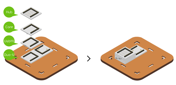
- Overlay Microduino-Core and Microduino-USBTTL together.
- Connect Microduino-USBTTL with USB cable, and prepare to upload the program.
- Note:Please upload programs before stacking all modules together.
- Open Arduino IDE for Microduino environment(Reference to set up:AVR Core:Getting started)
- Click [tool] bar, confirm board(Microduino-Core) processor(Atmega644pa@16M,5V) selected correctly, and select the corresponding port number(COMX).
- Click [File]->[open], browse to the project program address, and click “DBDetector.ino” to open it.
- After all these items are correct, click "→" button to download onto the development board.
Noise Detector Assemble
- Step1
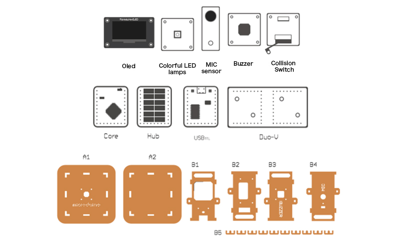
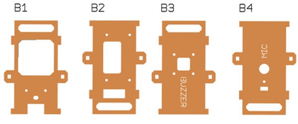
- Set them respectively in turn from left to right, namely structure B1,B2,B3,B4.
|
|
- Step2
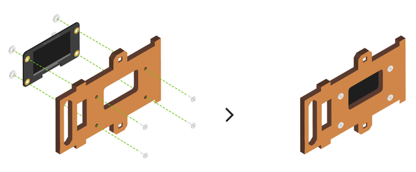
- Fix OLED on structure B2 with screw and nut, as shown in the picture.
|
|
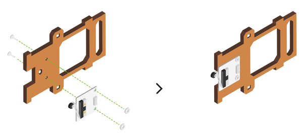
- Fix collision switch on structure B1 in accordance with the direction as shown in the picture.
- Note that it must be same with the direction on the picture, which is related to the overall placement of the collision switch.
|
|
- Step3
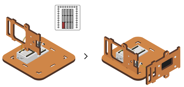
- Put structure B1 adjoining to structure B2.
- Make collision switch part in structure B1come out from the hollow-out part in structure B2, as shown in then picture marked.
|
|
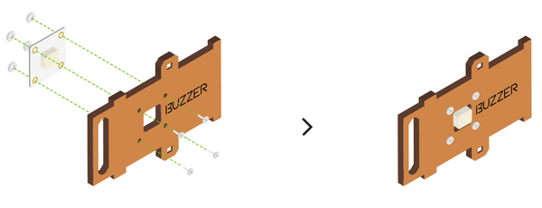
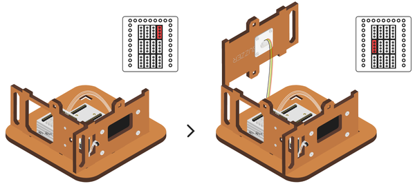
- Put structure B3 adjoining to structure B2.
|
|
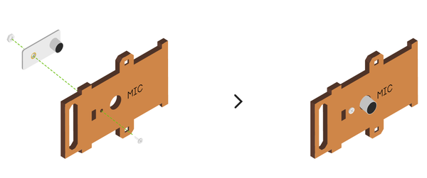
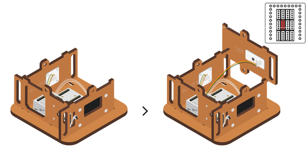
- Put structure B4 adjoining to structure B3.
|
|
- Step5
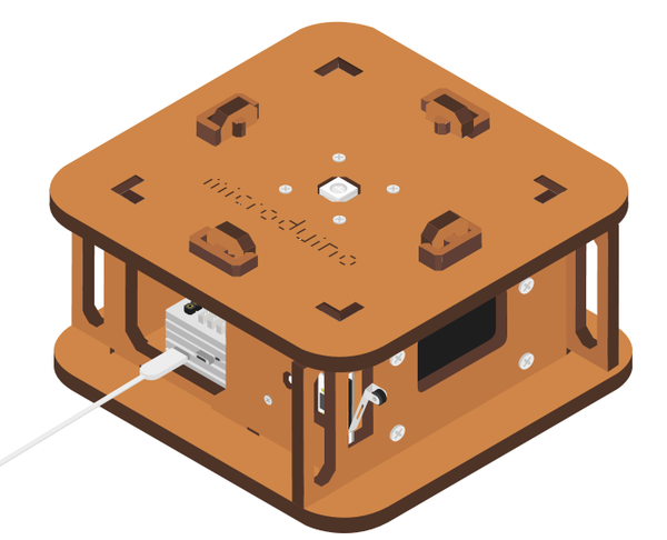
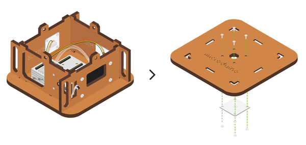
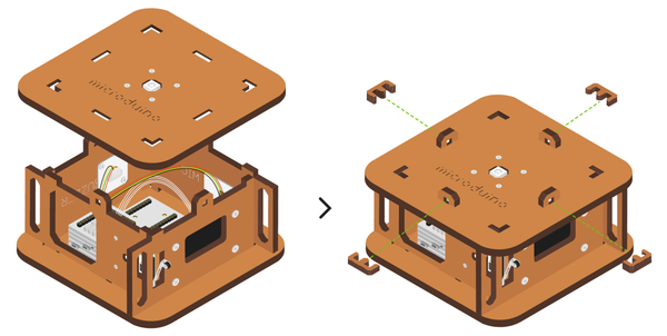
- Cover structure A1 and structure A2 up and down and fix with cart slot of structure B5 . Now the noise monitor assembling complete.
|
|
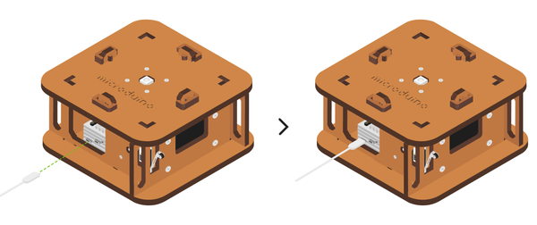
- Finally, insert USB cable into the power supply backplane of Microduino-Duo-v , then the noise tester can operate.
|
|
Operating Instruction
- When noise reaches a certain degree, it will give an alarm.
- The buzzer will ring, and the LED lamp will light.
- OLED will show the highest decibels.
- You can press the collision switch to turn off.
FAQ
- Q:Can the triggered sound size and duration be changed?
- A:Yes, you can change the variable value of voice and maxNoise in userDef.h.
- Q:Can I close it when the alarm ring?
- A:Yes, pressing the switch can close it.
- Q:Why dose mine continually alarm, and turning off the switch has no reaction?
- A:Notice that if the pin of microphone MIC has been inserted into A0/A1, and not into D0/D1, where is confusing.
|
