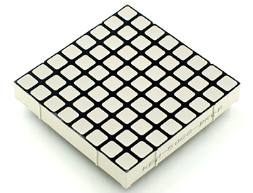
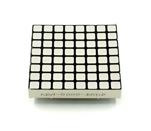
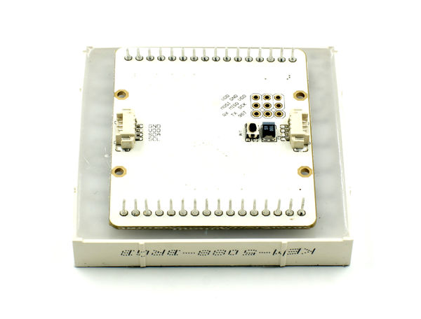
Microduino-Dot Matrix is a 8x8 colorful LED dot matrix displaying module, which can be used singly or by the cascade of multiple(combine into different shapes), to display text or images, or even simple animation.
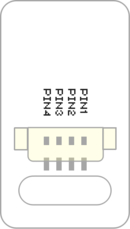
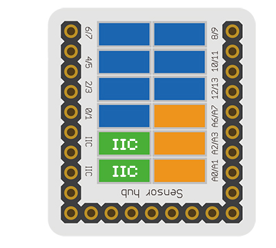
- General Pin Out is the standard pin out of a Sensor / Trinket connector.
- Sensor / Trinket's Pin Out is this specific Sensor / Trinket's wiring in relation to the General Pin Out.
- SIGNAL-A / SIGNAL-B are signals that could be digital input, digital output, analog input or analog output. Or special signals such as serial communication (SoftwareSerial, IIC (I2C), etc) or other special signals.
- Not Connected refers to the Pin not being used for this particular Sensor / Trinket.
- Read more about the hub module.
- Sensor voltage
- Sensor current
- Sensor size
- Size of the board: 60mm*60mm
- 1.27mm-spacing 4Pin interface connected with sensorhub
- Function description
- 8x8 dot matrix
- The display quality of the color of each point is 15-level, three RGB primary colors are 32-grade adjustable, and the whole is 32k-color to display.
- Supports IIC communication protocol, the IIC address is settable(1~64), and the dot matrix sequence adopts rectangular plane coordinate system.
- With 2 IIC interfaces onboard, which make the cascade of multiple dot matrix easy.
- Connection
- This sensor can be connected to the I2C interface of the core.
- The cascade of multiple sensors is supported, 64 at most.
Documents
Development
Program Download
Programming
Hardware Setup
- Referring to the following diagram, connect the Sensor-Dot Matrix-Color to the port I2C of Microduino-Sensorhub.
Method to Set the Address of the Dot Matrix
- The range of the address of the dot matrix is 1~64.
- After being powered, the number of the green points displayed on the dot matrix represents the address of the dot matrix.
- During 3s after the dot matrix is powered, pressing the button on the back can enter address configuration state, and at this time, the dot matrix changes into white.
- Pressing the button slowly (the interval is larger than 0.5s)will add the address
- Pressing the button quickly(the interval is less than 0.5s)will reduce the address
- After setting the address, long press the button for 3s, to exit the address configuration state.
Introduction of the Code
- Define the IIC address of single dot matrix
 uint8_t Addr[MatrixPix_X][MatrixPix_Y] = {  //1x1
   { 64}
 };
- Define the IIC address of 2x2 cascade dot matrix.
 uint8_t Addr[MatrixPix_X][MatrixPix_Y] = {  //2x2
   { 64, 63},
   { 62, 61}
 };
- Define the IIC address of 1x4 cascade dot matrix.
 uint8_t Addr[MatrixPix_X][MatrixPix_Y] = {  //1x4
   { 64, 63, 62 , 61}
 };
- Get the number of devices which have already been connected.
int16_t getMatrixNum()
- Get the IIC address of devices which have already been connected.
getDeviceAddr(_a) //num
- Get the number of the dot matrix on X axis.
getWidth()
- Get the number of the dot matrix on Y axis.
getHeight()
- Set the on or off of the dot matrix coordinate pixel.
setLed(_row, _col, _state) //row, col, state
- Set the color of the dot matrix coordinate pixel.
setLedColor(_row, _col, _r, _g, _b) //row, col, red, green ,blue
clearDisplay()
- Set the color of the dot matrix.
setColor(_r, _g, _b) //red, green ,blue
- The characters are displayed flowingly.
writeString(_c, _t, _col) //[char*], time, col
drawBMP(_row, _col , _w, _h, logo) //row, col, width, height, file
drawBMP(_row, _col, logo) //row, col, file
- Use function to draw a solid rectangle
drawBox(_row, _col, _w, _h) //row, col, width, height
- Draw a solid rounded rectangle.
drawRBox(_row, _col, _w, _h, _r) //row, col, width, height, rad
drawFrame(_row, _col, _w, _h) //row, col, width, height
- Draw a rounded hollow rounded rectangle
drawRFrame(_row, _col, _w, _h, _r) //row, col, width, height, rad
drawCircle(_row, _col, _r) //row, col, rad
drawDisc(_row, _col, _r) //row, col, rad
drawLine(_row, _col, _row1, _col1) //row start, col start, row end, col end
Application
Gallery
