Microduino-Dot Matrix-S2 is a 8x8 single color LED dot matrix displaying module, which can be used singly or by the cascade of multiple(combine into different shapes), to display text or images, or even simple animation.
- General Pin Out is the standard pin out of a Sensor / Trinket connector.
- Sensor / Trinket's Pin Out is this specific Sensor / Trinket's wiring in relation to the General Pin Out.
- SIGNAL-A / SIGNAL-B are signals that could be digital input, digital output, analog input or analog output. Or special signals such as serial communication (SoftwareSerial, IIC (I2C), etc) or other special signals.
- Not Connected refers to the Pin not being used for this particular Sensor / Trinket.
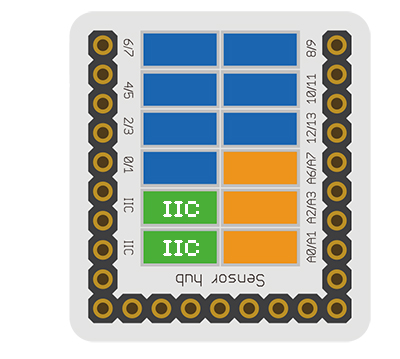
- Read more about the hub module.
- Sensor voltage
- Sensor current
- Sensor size
- Size of the board: 60mm*60mm
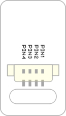
- 1.27mm-spacing 4Pin interface connected with sensorhub
- Function description
- 8x8 dot matrix
- The brightness of each point is 32-grade adjustable
- Supports IIC communication protocol, the IIC address is settable(1~64), and the dot matrix sequence adopts rectangular plane coordinate system.
- With 2 IIC interfaces onboard, which make the cascade of multiple dot matrix easy.
- Connection
- This sensor can be connected to the I2C interface of the core.
- The cascade of multiple sensors is supported, 64 at most.
Documents
Development
Program Download
Programming
Hardware Setup
- Referring to the following diagram, connect the Sensor-Dot Matrix-S2 to the I2C interface of Microduino-Sensorhub.
Method to Set the Address of the Dot Matrix
- The range of the address of the dot matrix is 1~64.
- After being powered, the number of the green points displayed on the dot matrix represents the address of the dot matrix.
- During 3s after the dot matrix is powered, pressing the button on the back can enter address configuration state, and at this time, the dot matrix changes into white.
- Pressing the button slowly (the interval is larger than 0.5s)will add the address
- Pressing the button quickly(the interval is less than 0.5s)will reduce the address
- After setting the address, long press the button for 3s, to exit the address configuration state.
Introduction of the Code
- Define the IIC address of single dot matrix.
 uint8_t Addr[MatrixPix_X][MatrixPix_Y] = {  //1x1
   { 64}
 };
- Define the IIC address of 2x2 cascade dot matrix.
 uint8_t Addr[MatrixPix_X][MatrixPix_Y] = {  //2x2
   { 64, 63},
   { 62, 61}
 };
- Define the IIC address of 1x4 cascade dot matrix.
 uint8_t Addr[MatrixPix_X][MatrixPix_Y] = {  //1x4
   { 64, 63, 62 , 61}
 };
- Get the number of devices which have already been connected.
int16_t getMatrixNum()
- Get the IIC address of devices which have already been connected
getDeviceAddr(_a) //num
- Get the number of the dot matrix on X axis.
getWidth()
- Get the number of the dot matrix on Y axis.
getHeight()
- Set the on or off of the dot matrix coordinate pixel
setLed(_row, _col, _state) //row, col, state
- Set the brightness of the dot matrix coordinate pixel
setLedBrightness(_row, _col, _value) //row, col, value
clearDisplay()
- Set the brightness of the dot matrix
setBrightness(_value) //value
- The characters are displayed as follow
writeString(_c, _t, _col) //[char*], time, col
drawBMP(_row, _col , _w, _h, logo) //row, col, width, height, file
drawBMP(_row, _col, logo) //row, col, file
- Use function to display a solid rectangle
drawBox(_row, _col, _w, _h) //row, col, width, height
- Draw a solid rounded rectangle.
drawRBox(_row, _col, _w, _h, _r) //row, col, width, height, rad
drawFrame(_row, _col, _w, _h) //row, col, width, height
- Draw a rounded hollow rounded rectangle
drawRFrame(_row, _col, _w, _h, _r) //row, col, width, height, rad
drawCircle(_row, _col, _r) //row, col, rad
drawDisc(_row, _col, _r) //row, col, rad
drawLine(_row, _col, _row1, _col1) //row start, col start, row end, col end
Application
Gallery

