Difference between revisions of "Sensor-Color LED"
From Microduino Wiki
(Created page with "{{Language|Microduino-Color LED}} {| style="width: 800px;" |- | 400px|thumb|right| Microduino-Lantern Microduino-Color LED is one-wire-bu...") |
|||
| Line 1: | Line 1: | ||
| − | {{Language|Microduino-Color | + | {{Language|Microduino-Color led}} |
{| style="width: 800px;" | {| style="width: 800px;" | ||
|- | |- | ||
| | | | ||
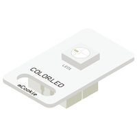
| − | [[File: Microduino-WS2812-rect.jpg|400px|thumb|right| Microduino- | + | [[File: Microduino-WS2812-rect-v1.jpg|400px|thumb|right| Microduino-Color led]] |
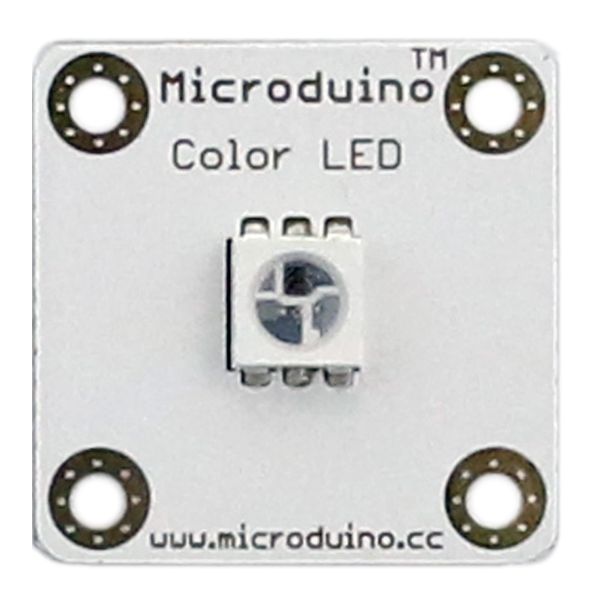
| − | Microduino-Color LED | + | Microduino-Color LED with an built-in IC control chip can be cascaded arbitrarily. With one I/O port, you can control all the lights and each light can be controlled separately. |
| Line 15: | Line 15: | ||
| − | + | ==Features== | |
| − | + | *The chip adopts 5050 package, including control circuit and RGB chip inside. | |
| − | + | *With single bus control, you only need one I/O port to receive data and decode; | |
| − | == | + | *With built-in IC control, serial cascading interface, it can have cascade control. |
| − | * | + | *Each pixel's trichromatic color can achieve 256-level brightness control, completing full display of 16,777,216 colors and the scanning frequency is not less than 400Hz/s; |
| − | * | + | *With built-in power-on and off reset circuits; |
| − | * | + | *ultra low power and ultra long life. |
==Specification== | ==Specification== | ||
| − | *3.3V~5V | + | * Electrical specification |
| − | *Size: | + | **Operation voltage: 3.3V~5V |
| − | *1.27mm-pitch | + | **Output device |
| − | * | + | *Tech parameter |
| + | **Adopt WS2812 integrated light source control; | ||
| + | **Each pixel's RGB can realize 256-level brightness display. | ||
| + | **When refresh rate is 30 frame/s, the cascade number is not less than 1,024 points. | ||
| + | **When the transmission distance of any two points is within three meters, there is no need to add any circuit. | ||
| + | *Size | ||
| + | **Size of LED:5mm*5mm, | ||
| + | **Size of the board:20mm*20mm | ||
| + | **1.27mm-pitch 4Pin interface connects with Sensorhub. | ||
| + | *Connection method | ||
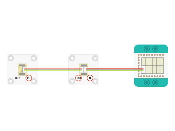
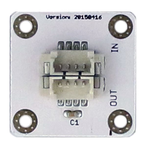
| + | **System and LED(<big>IN</big>):System LED control needs to connect the signal of Sensorhub to the " big>IN</big>" base board of the LED. | ||
| + | **LED Cascade(<big>OUT</big>): The first LED's <big>OUT</big> connects to the next LED's <big>IN</big>. | ||
| − | [[File: | + | [[File: CoreUSB_Ble_steup11.jpg|600px|center]] |
==Document== | ==Document== | ||
| + | [[File:ws2812.pdf]] | ||
| − | * | + | ==Development== |
| + | ===Preparation=== | ||
| + | *Make sure you build Microduino development environment. If not, please refer to: [[Microduino Getting started]] | ||
| + | *Core selection | ||
| + | **1. Adopt [[Microduino-CoreUSB]] or [[mCookie-CoreUSB]]. | ||
| + | **2.Adopt [[Microduino-Core]] or [[Microduino-Core+]] as the core board and use [[Microduino-USBTTL]] to download program. | ||
| + | ===Program=== | ||
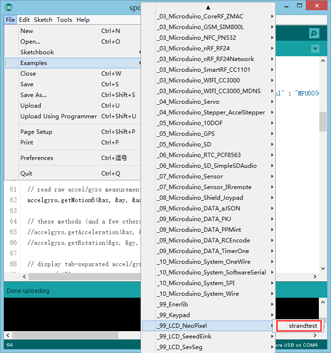
| + | *Open " strandtext " in the libraries. | ||
| + | [[file:mCookie-strandtext.JPG|thumb|800px|center]] | ||
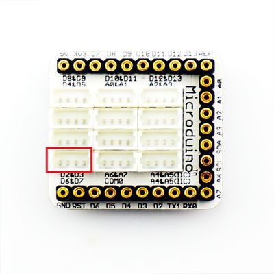
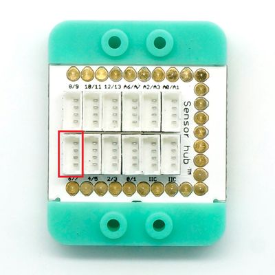
| + | *"#define PIN 6" defines the pin which controls LED. "6" means Microduino's D6 pin, which can be converted by Sensorhub. Users can also change that according to personal needs. | ||
| + | *The number "60" in " Adafruit_NeoPixel strip = Adafruit_NeoPixel(60, PIN, NEO_GRB + NEO_KHZ800);" is the light number you want to cascade. | ||
| + | *" colorWipe(uint32_t c, uint8_t wait)" Function Description: | ||
| + | **" uint32_t c " defines the color of the lights and the format is " strip.Color(R, G, B)". | ||
| + | ***R:Value of red(0-255) | ||
| + | ***G:Value of green(0-255) | ||
| + | ***B:Value of green(0-255) | ||
| + | **" uint8_t wait " defines delay time of a single light. The light number is defined at the beginning. | ||
| + | **Example: colorWipe(strip.Color(255, 0, 0), 50); Display red. | ||
| + | **Users can adopt the related tools to change color | ||
| + | [http://www.atool.org/colorpicker.php color]。 | ||
| + | *“rainbow()” and “rainbowCycle()” are cool color pattern. | ||
| − | == | + | ===Hardware Buildup=== |
| − | + | *Connect '''IN''' port on the back of the color LED to the D6 digital port of Sensorhub, which is also the definition and control of LED pins mentioned above. (Users can change according to personal needs.) | |
| + | [[Microduino-Sensorhub]] | ||
| + | [[file:Microduino-sensorhub_6.JPG|thumb|400px|center]] | ||
| + | [[mCookie-Hub]] | ||
| + | [[file:mCookie-sensorhub_6.JPG|thumb|400px|center]] | ||
| + | *Connect the core board, Sensorhub and LED to a computer via a USB cable. | ||
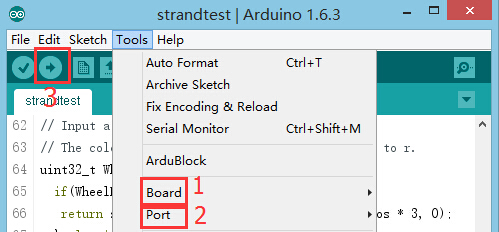
| + | *Select the right board and COM port, compile and download. Please refer to: [[AVR Core:Getting started]] | ||
| + | [[file:upload.JPG|thumb|800px|center]] | ||
| + | *You can see result after download. | ||
| + | |||
| + | ==Project== | ||
| + | * '''[[Birthday Lamp]]''' | ||
| + | * '''[[Bluetooth Lamp]]''' | ||
| + | * '''[[Rhythm Lamp]]''' | ||
| + | * '''[[Applause Enthusiasm Detection]]''' | ||
| + | * '''[[Colored LED]]''' | ||
| − | |||
| − | |||
| − | |||
| − | |||
| − | |||
| − | |||
| − | |||
| − | |||
| − | |||
| − | |||
==Purchase== | ==Purchase== | ||
| Line 53: | Line 90: | ||
==Picture== | ==Picture== | ||
| − | + | *Front | |
| − | *Front | ||
[[file: Microduino-Lantern-F.JPG|thumb|600px|center|Microduino-Cube-Station Front]] | [[file: Microduino-Lantern-F.JPG|thumb|600px|center|Microduino-Cube-Station Front]] | ||
| − | *Back | + | *Back |
[[file: Microduino-Lantern -b.JPG|thumb|600px|center|Microduino-Cube-Station Back]] | [[file: Microduino-Lantern -b.JPG|thumb|600px|center|Microduino-Cube-Station Back]] | ||
|} | |} | ||
Revision as of 09:52, 22 October 2015
| Language: | English • 中文 |
|---|
|
Microduino-Color LED with an built-in IC control chip can be cascaded arbitrarily. With one I/O port, you can control all the lights and each light can be controlled separately.
Contents[hide]Features
Specification
DocumentDevelopmentPreparation
Program
Hardware Buildup
ProjectPurchaseHistoryPicture
|
