Difference between revisions of "MCookie 102 Basic Kit Tutorials"
From Microduino Wiki
(→Printed Manual) |
(→Step 3: Configuring and Testing the Software) |
||
| Line 17: | Line 17: | ||
# Go to “Tools > Board” and select “Microduino/mCookie-device” <br> [[File:Software_Setup_Guide_Select_Board.png|frame|left]]<br clear=all> | # Go to “Tools > Board” and select “Microduino/mCookie-device” <br> [[File:Software_Setup_Guide_Select_Board.png|frame|left]]<br clear=all> | ||
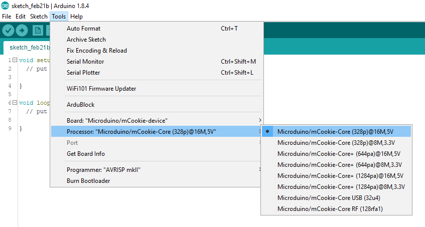
# Go to “Tools > Processor” and select “Microduino/mCookie-Core (328p)@16M,5V” <br> [[File:Software_Setup_Guide_Select_Processor.png|frame|left]]<br clear=all> | # Go to “Tools > Processor” and select “Microduino/mCookie-Core (328p)@16M,5V” <br> [[File:Software_Setup_Guide_Select_Processor.png|frame|left]]<br clear=all> | ||
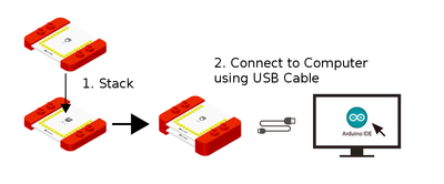
| − | # Only have the red Core module and USBTTL module stacked. Then connect the MicroUSB to the USBTTL module and the other end to your computer's USB port. <br> [[File:Core%2BUSBTTL_connect.png|thumb|left|400px]]<br clear=all> | + | # Only have the red Core module and USBTTL module stacked. Then connect the MicroUSB cable to the USBTTL module and the other end to your computer's USB port. <br> [[File:Core%2BUSBTTL_connect.png|thumb|left|400px]]<br clear=all> |
# Check if the red LED is lit on the USBTTL module. This indicates the USBTTL is ON and SUPPLYING power to the modules. | # Check if the red LED is lit on the USBTTL module. This indicates the USBTTL is ON and SUPPLYING power to the modules. | ||
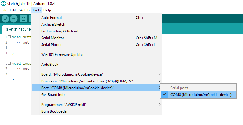
# Go to “Tools > Port” and select the port. It is usually the one that is select-able. (If you are using a Mac, it is not the Bluetooth one) <br> [[File:Software_Setup_Guide_Select_Port_Selection.png|frame|left]]<br clear=all> | # Go to “Tools > Port” and select the port. It is usually the one that is select-able. (If you are using a Mac, it is not the Bluetooth one) <br> [[File:Software_Setup_Guide_Select_Port_Selection.png|frame|left]]<br clear=all> | ||
| Line 29: | Line 29: | ||
Printed manual download: [http://wiki.microduinoinc.com/images/c/c4/102_Basic_Kit_English.compressed.pdf Link] | Printed manual download: [http://wiki.microduinoinc.com/images/c/c4/102_Basic_Kit_English.compressed.pdf Link] | ||
| + | |||
=Projects= | =Projects= | ||
<div style="width:80%; float:left"> | <div style="width:80%; float:left"> | ||
Revision as of 16:37, 5 March 2018
Contents
Getting Started
Step 1: Downloading Latest Software
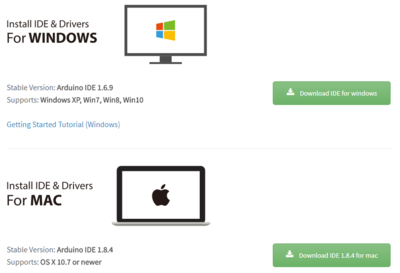
Download the latest Microduino software for your OS (Windows or Mac) at: http://microduinoinc.com/download/
Step 2: Follow the Software Getting Started Guide
Follow the getting software started guide for your OS at:
Follow the guide to ensure the software is properly setup and the correct drivers are installed.
Step 3: Configuring and Testing the Software
- Open the Microduino software.
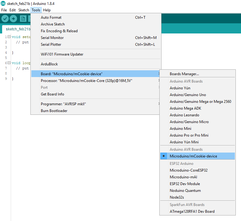
- Go to “Tools > Board” and select “Microduino/mCookie-device”
- Go to “Tools > Processor” and select “Microduino/mCookie-Core (328p)@16M,5V”
- Only have the red Core module and USBTTL module stacked. Then connect the MicroUSB cable to the USBTTL module and the other end to your computer's USB port.
- Check if the red LED is lit on the USBTTL module. This indicates the USBTTL is ON and SUPPLYING power to the modules.
- Go to “Tools > Port” and select the port. It is usually the one that is select-able. (If you are using a Mac, it is not the Bluetooth one)
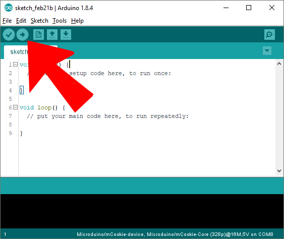
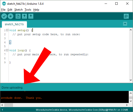
- With the default sample code. Hit upload (right arrow icon on the top left of the software).
- The code will compile and will say upload complete if successful. Congratulations the software setup is complete!
Example projects for the 102 Basic kit can be found in the #Projects section.
Printed manual download: Link
Projects
Basic Tutorials
Basic Module Tutorials
| Core | Communication |
|---|---|
| Function | Extension |
