Difference between revisions of "Open Source WiFi Weather Station"
From Microduino Wiki
(→Step 6) |
(→Other Equipment) |
||
| (15 intermediate revisions by the same user not shown) | |||
| Line 1: | Line 1: | ||
| − | |||
| − | |||
| − | |||
==Outline== | ==Outline== | ||
*Project: Open Source WIFI Weather Station System.(ESP8266 connected to Blynk) | *Project: Open Source WIFI Weather Station System.(ESP8266 connected to Blynk) | ||
| Line 68: | Line 65: | ||
|Shell ||1|| | |Shell ||1|| | ||
|} | |} | ||
| − | [[File:weatherStationMatiralAll.png||1000px | + | [[File:weatherStationMatiralAll.png||1000px]] |
{| class="wikitable" style="background-color:#FEF9E7;" | {| class="wikitable" style="background-color:#FEF9E7;" | ||
| Line 102: | Line 99: | ||
==Using the Blynk App== | ==Using the Blynk App== | ||
| − | On the main screen of the Blynk app. Click on the '''QR code scanner''' to scan the Weather Station app. | + | *On the main screen of the Blynk app. Click on the '''QR code scanner''' to scan the Weather Station app. |
| + | ::[[File:wws_qr_scan.png|300px]] | ||
| − | |||
| − | Scan the QR code below. | + | *Scan the QR code below. |
| + | ::[[File:Wws_qr_code.png|300px]] | ||
| − | |||
| − | Once the project has loaded, click on '''Project Settings''' (nut icon). | + | *Once the project has loaded, click on '''Project Settings''' (nut icon). |
| + | ::[[File:wws_project_settings.png|300px]] | ||
| − | |||
| − | Under Auth Tokens, click on '''Email all'''. This will send the authentication token to your registered e-mail. Make note of this, as you will need this token later. | + | *Under Auth Tokens, click on '''Email all'''. This will send the authentication token to your registered e-mail. Make note of this, as you will need this token later. |
| + | ::[[File:wws_auth_token.png|300px]] | ||
| − | |||
| − | Click back to return to the Weather Station app. | + | *Click back to return to the Weather Station app. |
| − | + | ::[[File:Wws_weather_app.png|300px]] | |
| − | [[ | ||
==Programming== | ==Programming== | ||
| Line 145: | Line 141: | ||
**'''PASS''' (WiFi password) | **'''PASS''' (WiFi password) | ||
**'''auth''' key as noted earlier in the Blynk app sent to you via e-mail. | **'''auth''' key as noted earlier in the Blynk app sent to you via e-mail. | ||
| + | :::[[File:Wws_configuration.png|500px]] | ||
*Click on the '''upload button''' (right arrow icon on the top left) to upload the program. | *Click on the '''upload button''' (right arrow icon on the top left) to upload the program. | ||
*The program will compile and upload. Once completed a upload successful message will appear on the bottom left. | *The program will compile and upload. Once completed a upload successful message will appear on the bottom left. | ||
| Line 151: | Line 148: | ||
===Step 1=== | ===Step 1=== | ||
*Fixate [[Microduino-OLED]] and '''Structure-A1''' with screws. | *Fixate [[Microduino-OLED]] and '''Structure-A1''' with screws. | ||
| − | [[File:Waetherstep1.jpg||600px | + | [[File:Waetherstep1.jpg||600px]] |
===Step 2=== | ===Step 2=== | ||
*Assemble '''Structure-B1~B5''' with '''Structure-B6'''. | *Assemble '''Structure-B1~B5''' with '''Structure-B6'''. | ||
| − | [[File:Waetherstep2.jpg||600px | + | [[File:Waetherstep2.jpg||600px]] |
===Step 3=== | ===Step 3=== | ||
| Line 165: | Line 162: | ||
**[[Microduino-Core+]] | **[[Microduino-Core+]] | ||
**[[Microduino-USBTTL]] | **[[Microduino-USBTTL]] | ||
| − | **[[Microduino-Sensorhub]] | + | **[[Microduino-WiFi]] |
| + | **[[Microduino-Sensorhub]] (on the very top of the stack) | ||
*Attach the included adhesive strip onto the '''PM2.5 Sensor''' GP2Y1010AU0F, then to the base board. | *Attach the included adhesive strip onto the '''PM2.5 Sensor''' GP2Y1010AU0F, then to the base board. | ||
| − | [[File:Waetherstep3.jpg||600px | + | [[File:Waetherstep3.jpg||600px]] |
===Step 4=== | ===Step 4=== | ||
| Line 177: | Line 175: | ||
**Air quality detector ([[Microduino-Air Quality]]) | **Air quality detector ([[Microduino-Air Quality]]) | ||
**Light sensor ([[Microduino-Light]]) | **Light sensor ([[Microduino-Light]]) | ||
| − | [[File:Waetherstep4.jpg||600px | + | [[File:Waetherstep4.jpg||600px]] |
===Step 5=== | ===Step 5=== | ||
| Line 191: | Line 189: | ||
*Refer to the picture below, stack all sensors on the slot of '''Structure-B1''' and '''Structure-B2'''. | *Refer to the picture below, stack all sensors on the slot of '''Structure-B1''' and '''Structure-B2'''. | ||
*After that, connect '''Structure-A1''' and '''Structure-A2''' at the top and bottom of the system respectively. | *After that, connect '''Structure-A1''' and '''Structure-A2''' at the top and bottom of the system respectively. | ||
| − | [[File:Waetherstep5.jpg||600px | + | [[File:Waetherstep5.jpg||600px]] |
===Step 6=== | ===Step 6=== | ||
| Line 197: | Line 195: | ||
===Step 7=== | ===Step 7=== | ||
| − | * | + | *Power on the Weather Station. |
| − | * | + | *The Weather Station will connect to the WiFi network. This may take a minute or so. |
| − | [[File: | + | *After connecting, the OLED screen will display the sensor data. |
| + | *If the data does not display, check the serial port in the IDE. It should display debugging information. | ||
| + | |||
| + | ===Step 8=== | ||
| + | *If the Weather Station successfully connect to the WiFi network. You can now view the data on the Blynk Phone app. | ||
| + | **WiFi Weather Station successfully connected to the WiFi network. | ||
| + | ::[[File:Wws_connected_to_wifi.png|Wws_connected_to_wifi.png]] | ||
| + | |||
| + | |||
| + | *Return to your phone which is running Blynk. Open the Weather Station project. Click on Start (play icon). | ||
| + | ::[[File:Wws_start_project.png|300px]] | ||
| + | |||
| + | |||
| + | *The sensor data should start streaming to the Blynk app. | ||
| + | ::[[File:Wws_project_running.png|300px]] | ||
==Notes== | ==Notes== | ||
*Please make sure the verification code is configured right. | *Please make sure the verification code is configured right. | ||
| − | *Make sure your router runs normally, the SSID and password are correct. | + | *Make sure your router runs normally, the SSID and password are correct. |
| − | |||
| − | |||
Latest revision as of 02:34, 19 December 2018
Contents
Outline
- Project: Open Source WIFI Weather Station System.(ESP8266 connected to Blynk)
- Objective: To get temperature, humidity, light intensity and PM2.5 at the weather station.
- Note: PM2.5 refers to atmospheric particulate matter (PM) that have a diameter of less than 2.5 micrometers
- Difficulty: Medium
- Time-consuming: 2-Hour
- Maker: Ray
Introduction:
- Read temperature, humidity, light intensity and PM2.5 data and display those data on the screen.
- Upload the data to Blynk.
- View data on phone anywhere using the Blynk app.
- Created by Microduino with Microduino components.
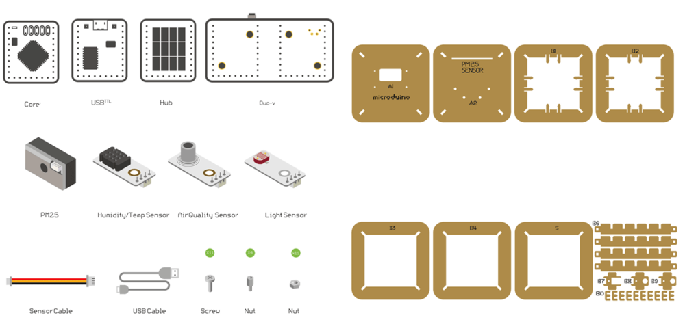
Bill of Material
Microduino Equipment
| Note: Different revisions may contain different components. |
| Module | Number | Function |
| Microduino-Core+ | 1 | Core board (Arduino) |
| Microduino-USBTTL -OR- Microduino-USBTLL-C | 1 | Programmer for Core board |
| Microduino-WIFI(ESP) | 1 | WiFi communication module |
| Microduino-Sensorhub | 1 | Connector Hub to connect sensors |
| Microduino-Duo-h -OR- Microduino-Cube-S1 | 1 | Extension board |
| Microduino-OLED | 1 | Display |
| Sensor | Number | Function |
| Microduino-Temp&Hum -OR- Sensor-Tem&Hum-S2 | 1 | Digital temperature and humidity sensor |
| Microduino-Air Quality | 1 | Air quality detector |
| Microduino-Light | 1 | Light-sensitive sensor |
| GP2Y1010AU0F | 1 | PM2.5 sensor |
Other Equipment
| Equipment | Number | Function |
| Micro-USB cable | 1 | For program download and power supply |
| GP2Y1010AU0F | 1 | PM2.5 sensor |
| Screw | 7 | Fixate modules |
| Screwdriver | 1 | Fixate screws |
| Shell | 1 |
| Note: Different revisions will contain different components.
Most noteable are:
|
Principle of the Experiment
This Weather Station can detect data including:
- Temperature and humidity via Microduino-Temp&Hum
- Light intensity via Microduino-Light
- Air quality via Microduino-Air Quality
- PM2.5 via GP2Y1010AU0F
Other functions:
- Use the Microduino-Core+ to analyze and process sensor data.
- Display data on the Microduino-OLED.
- Connect the Weather Station with Blynk via Microduino-WIFI(ESP).
- Each sensor connects with Microduino-Sensorhub.
Get and Configure Blynk
Next, we'll learn how Microduino interacts with Blynk through the configuration process of the Weather Station.
Download the Blynk App
Visit the Google Play Store or the Apple App Store and download the Blynk app.
You'll need to setup an account with Blynk before proceeding. Please use a valid e-mail as your authentication tokens will be sent to that e-mail.
Using the Blynk App
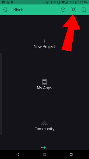
- On the main screen of the Blynk app. Click on the QR code scanner to scan the Weather Station app.
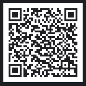
- Scan the QR code below.
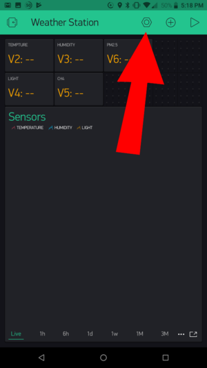
- Once the project has loaded, click on Project Settings (nut icon).
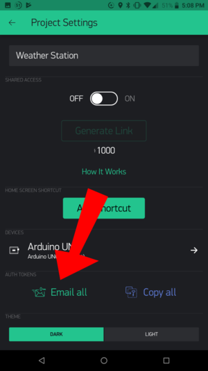
- Under Auth Tokens, click on Email all. This will send the authentication token to your registered e-mail. Make note of this, as you will need this token later.
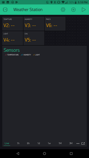
- Click back to return to the Weather Station app.
Programming
Software Setup
Please follow the guide to ensure your software is correctly setup. The software is required to program the WiFi Weather Station.
Download the latest software for your operating system and follow the getting started guides:
Programming the Weather Station
- Stack Microduino-Core+ and Microduino-USBTTL together.
- Connect Microduino-USBTTL with a USB cable. Connect the other end to the PC being used.
- Open the Arduino IDE for Microduino development environment. (Please refer to the #Software Setup section).
- Configure the software to upload to the Core+ module as follows:
- Tools > Board > Microduino/mCookie-device
- Tools > Processor > Microduino/mCookie-Core+ (644pa)@16M,5V
- Tools > Port > select the port (On MacOS, NOT the Bluetooth one).
- Download the code for Weather Station here: File:ESP8266BlynkWeatherStationV2.zip
- Unzip the file. Under the software (Arduino IDE), go to File > Open... and navigate to the unzipped folder and open the ESP8266BlynkWeatherStationV2.ino file.
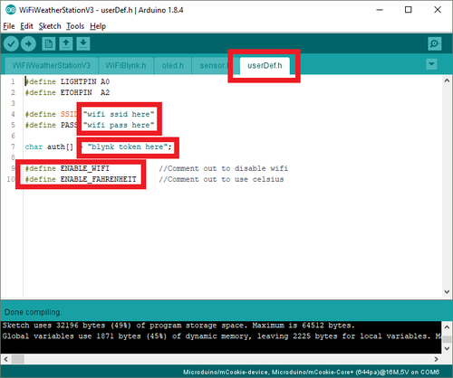
- The sketch with multiple files will open. Click on the userDef.h tab. You'll need to configure the WiFi connection (2.4GHz networks, non 5GHz) with:
- SSID
- PASS (WiFi password)
- auth key as noted earlier in the Blynk app sent to you via e-mail.
- Click on the upload button (right arrow icon on the top left) to upload the program.
- The program will compile and upload. Once completed a upload successful message will appear on the bottom left.
Hardware Buildup
Step 1
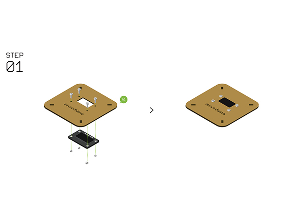
- Fixate Microduino-OLED and Structure-A1 with screws.
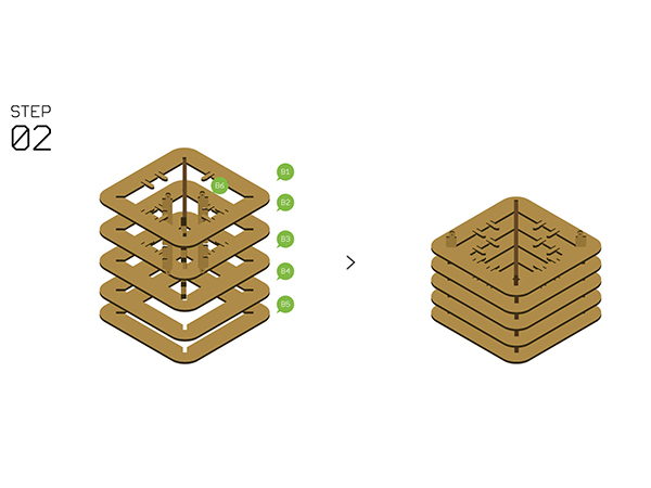
Step 2
- Assemble Structure-B1~B5 with Structure-B6.
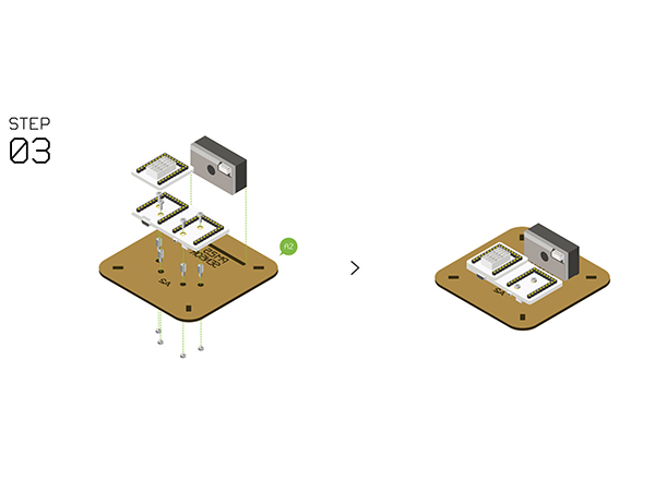
Step 3
| Note: Different revisions of this kit may contain different components. Either a Duo-H or Cube-S1 should be used. Duo-H is illustrated. |
- Fixate Microduino-Duo-h / Microduino-Cube-S1 on Structure-A2 with screws and nuts.
- Stack the following modules on Microduino-Duo-h / Microduino-Cube-S1.
- Microduino-Core+
- Microduino-USBTTL
- Microduino-WiFi
- Microduino-Sensorhub (on the very top of the stack)
- Attach the included adhesive strip onto the PM2.5 Sensor GP2Y1010AU0F, then to the base board.
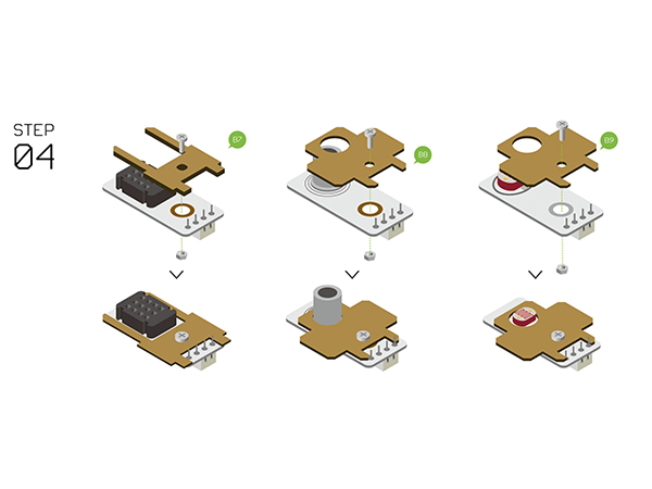
Step 4
| Note: Different revisions of this kit may contain different components. Either a Temp&Hum or Tem&Hum-S2 should be used. Temp&Hum is illustrated. |
- Assemble the following sensors with Structure-B7, B8, B9.
- Temperature and humidity sensor (Microduino-Temp&Hum / Tem&Hum-S2)
- Air quality detector (Microduino-Air Quality)
- Light sensor (Microduino-Light)
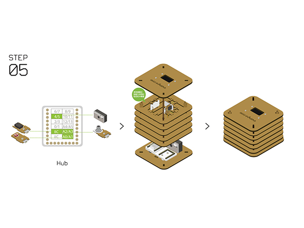
Step 5
| Note: Different revisions of this kit may contain different components. Either a Temp&Hum or Tem&Hum-S2 should be used. Temp&Hum is illustrated. |
- Connect the sensors below to Microduino-Sensorhub using a connector wire.
- Temperature and humidity sensor (Microduino-Temp&Hum / Tem&Hum-S2) to pin IIC.
- Air quality detector (Microduino-Air Quality) to pin A2/A3.
- Light sensor (Microduino-Light) to pin A0/A1.
- PM2.5 to pin 4/5.
- Refer to the picture below, stack all sensors on the slot of Structure-B1 and Structure-B2.
- After that, connect Structure-A1 and Structure-A2 at the top and bottom of the system respectively.
Step 6
- Complete the steps above, plug in a USB cable then fixate Structure-B0. Congratulations! You finished the buildup of the Weather Station.
Step 7
- Power on the Weather Station.
- The Weather Station will connect to the WiFi network. This may take a minute or so.
- After connecting, the OLED screen will display the sensor data.
- If the data does not display, check the serial port in the IDE. It should display debugging information.
Step 8
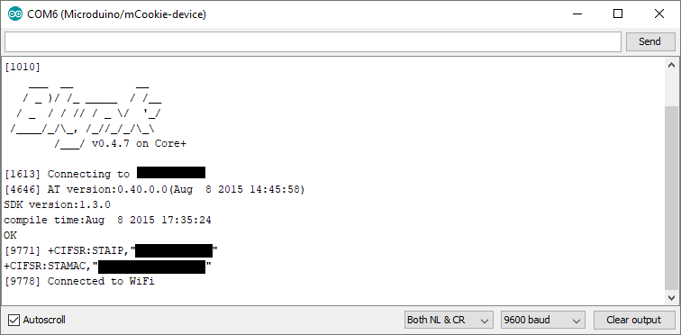
- If the Weather Station successfully connect to the WiFi network. You can now view the data on the Blynk Phone app.
- WiFi Weather Station successfully connected to the WiFi network.
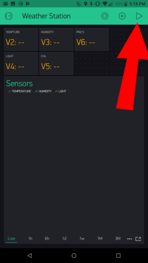
- Return to your phone which is running Blynk. Open the Weather Station project. Click on Start (play icon).
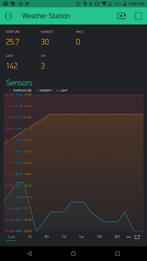
- The sensor data should start streaming to the Blynk app.
Notes
- Please make sure the verification code is configured right.
- Make sure your router runs normally, the SSID and password are correct.
