|
Microduino-Line-track is infrared module, which can be used to find line.
The detection principle of the black line is that the infrared transmitting tube emits light to the road, and the infrared light is reflected by the white floor, and the receiver receives the reflected light.
Instruction of the Sensor Pin
|
|
- Pins of the sensor:
- PIN1: GND
- PIN2: VCC
- General signal pins:
- PIN3(IO1): digital/analog signal
- PIN4(IO2): NC(null)
- Special signal pins:
- If it is IIC: IO1/IO2 are respectively SDA/SCL.
- If it is soft serial port: IO1/IO2 are respectively tx/rx.
|
Microduino sensor can communicate with core module through the connection with Microduino-Module Sensor Hub.
|
Features
- With high detection sensitivity and good stability
- With small size
Specification
- Electric specification
- 3.3V~5V working voltage
- Input device
- Technical parameters
- Introduction of pins: GND, VCC, signal output, and NC(null).
- Digital input
- Size
- Size of the switch: 5mm*10mm
- Size of the board: 20mm*10mm
- 1.27mm-spacing 4Pin interface
- Output: Digital signal
- Connection
- This output signal is digital signal, so it should be detected by signal ports(D0~D13). You can connect it to pin 3~10 of Sensor-hub, and the corresponding pins are D0, D2, D4, D6, D8, D10, D12.
Document
Development
Preparation
- Make sure that you have set up the development environment of Microduino, otherwise, please refer to: Microduino Getting started
- Core selection
Program
- Open Arduino IDE, choose File→Examples→Basics→DigitalReadSerial, the sample program, select the right board card, and download directly after compiling.
- int pushButton = 6; Define the input pin is D6, which is modifiable, such as linePin.
- pinMode(pushButton, INPUT); Define pushButton as input pin.
- int buttonState = digitalRead(pushButton); Read the value of the input pin pushButton.
Hardware Setup
- Connect sensor lineTrack with the digital port D6 of Sensorhub, which is the pin that define the pushButton above, which is modifiable, such as linePin.
- You can refer to : Microduino-Sensorhub
- Connect Sensorhub with lineTrack, and connect them to the computer with USB cable.
- Select the right board card and COM port, and directly download after compiling. You can refer to AVR Core:Getting Started
- After download, you can open the serial monitor. The returned value is “0” if there is no obstacle approaching to the sensor; if there is, the returned value is “1”, and through this it can judge whether there is something approaching to it.
Application
It can be used to detect obstacles and infrared emission, as a line finding sensor.
Purchase
History
Gallery
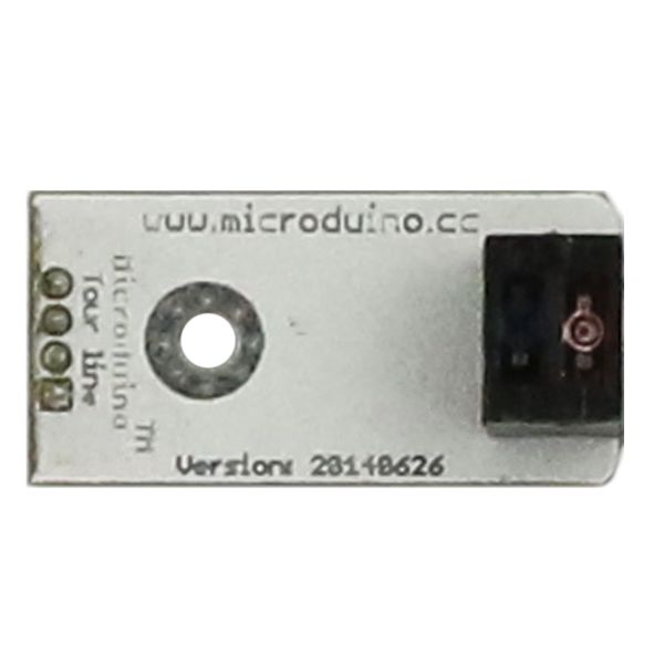 Microduino-Line-track Front 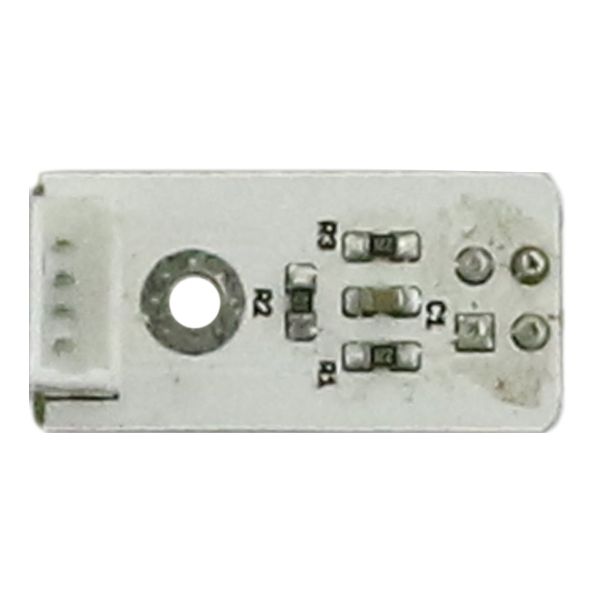 Microduino-Line-track Back |


