Difference between revisions of "Microduino Modules"
From Microduino Wiki
Microduino (talk | contribs) (→AVR Based) |
Microduino (talk | contribs) (→Other) |
||
| (41 intermediate revisions by the same user not shown) | |||
| Line 1: | Line 1: | ||
| − | + | =Microduino Specification= | |
| − | |||
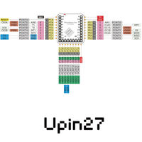
| − | = | + | ==Description of Upin27 Specification== |
| − | + | [[file:Microduino-Pin-readme.jpg|200px]] | |
| − | |||
| − | [[file:Microduino-Pin-readme.jpg|200px | ||
| − | |||
| − | |||
*'''[[Description of Upin27 Specification]]''' | *'''[[Description of Upin27 Specification]]''' | ||
| − | *Positive and | + | *Positive and negative views |
*Description of the size | *Description of the size | ||
| − | == | + | ==Pin Mappings== |
*'''[[Description of Microduino Upin27 Pins]]''' | *'''[[Description of Microduino Upin27 Pins]]''' | ||
*Pins usage | *Pins usage | ||
*I2C component address | *I2C component address | ||
| − | |||
| − | |||
| − | |||
| − | |||
| − | |||
| − | |||
| − | |||
| − | |||
| − | |||
| − | |||
=Core Modules= | =Core Modules= | ||
| Line 34: | Line 19: | ||
|header=Core | |header=Core | ||
|link=Microduino-Module_Core | |link=Microduino-Module_Core | ||
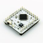
| − | |image=File:Microduino | + | |image=File:Microduino-Main.jpg |
|image_size=140px|table_width=175px|table_height=150px | |image_size=140px|table_width=175px|table_height=150px | ||
}} | }} | ||
| Line 48: | Line 33: | ||
|header=CoreUSB | |header=CoreUSB | ||
|link=Microduino-Module_CoreUSB | |link=Microduino-Module_CoreUSB | ||
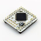
| − | |image=File:Microduino | + | |image=File:Microduino-core32U4-rect-nologo.jpg |
|image_size=140px|table_width=175px|table_height=150px | |image_size=140px|table_width=175px|table_height=150px | ||
}} | }} | ||
| Line 93: | Line 78: | ||
|header=Core LPC | |header=Core LPC | ||
|link=Microduino-Module_Core_LPC | |link=Microduino-Module_Core_LPC | ||
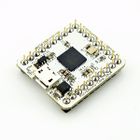
| − | |image=File:Microduino | + | |image=File:Microduino-_CoreSTM32_-rect.jpg |
|image_size=140px|table_width=175px|table_height=150px | |image_size=140px|table_width=175px|table_height=150px | ||
}} | }} | ||
| Line 100: | Line 85: | ||
|header=Core MK22 | |header=Core MK22 | ||
|link=Microduino-Module_Core_MK22 | |link=Microduino-Module_Core_MK22 | ||
| − | |image=File:Microduino | + | |image=File:Microduino-_CoreSTM32_-rect.jpg |
|image_size=140px|table_width=175px|table_height=150px | |image_size=140px|table_width=175px|table_height=150px | ||
}} | }} | ||
| Line 107: | Line 92: | ||
|header=Core EFM32 | |header=Core EFM32 | ||
|link=Microduino-Module_Core_EFM32 | |link=Microduino-Module_Core_EFM32 | ||
| − | |image=File:Microduino | + | |image=File:Microduino-_CoreSTM32_-rect.jpg |
|image_size=140px|table_width=175px|table_height=150px | |image_size=140px|table_width=175px|table_height=150px | ||
}} | }} | ||
| Line 136: | Line 121: | ||
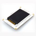
|header=TFT | |header=TFT | ||
|link=Microduino-Module_TFT | |link=Microduino-Module_TFT | ||
| − | |image=File:Microduino | + | |image=File:Microduino-tft-rect-nologo.jpg |
|image_size=140px|table_width=175px|table_height=150px | |image_size=140px|table_width=175px|table_height=150px | ||
}} | }} | ||
| Line 149: | Line 134: | ||
|header=Motor | |header=Motor | ||
|link=Microduino-Module_Motor | |link=Microduino-Module_Motor | ||
| − | |image=File:Microduino | + | |image=File:Microduino-a3906-rect-nologo.jpg |
|image_size=140px|table_width=175px|table_height=150px | |image_size=140px|table_width=175px|table_height=150px | ||
}} | }} | ||
| Line 156: | Line 141: | ||
|header=Stepper | |header=Stepper | ||
|link=Microduino-Module_Stepper | |link=Microduino-Module_Stepper | ||
| − | |image=File:Microduino | + | |image=File:Microduino-a4982-rect-nologo.jpg |
|image_size=140px|table_width=175px|table_height=150px | |image_size=140px|table_width=175px|table_height=150px | ||
}} | }} | ||
| Line 202: | Line 187: | ||
|header=Audio | |header=Audio | ||
|link=Microduino-Module_Audio | |link=Microduino-Module_Audio | ||
| − | |image=File: | + | |image=File:Audio-nologo.png |
|image_size=140px|table_width=175px|table_height=150px | |image_size=140px|table_width=175px|table_height=150px | ||
}} | }} | ||
| Line 209: | Line 194: | ||
|header=AudioPro | |header=AudioPro | ||
|link=Microduino-Module_AudioPro | |link=Microduino-Module_AudioPro | ||
| − | |image=File:Microduino | + | |image=File:Microduino-AudioPro-rect.jpg |
|image_size=140px|table_width=175px|table_height=150px | |image_size=140px|table_width=175px|table_height=150px | ||
}} | }} | ||
| Line 265: | Line 250: | ||
|header=Ethernet, WIZ | |header=Ethernet, WIZ | ||
|link=Microduino-Module_Ethernet,WIZ | |link=Microduino-Module_Ethernet,WIZ | ||
| − | |image=File:Microduino | + | |image=File:Microduino-W5500-nologo-rect.png |
|image_size=140px|table_width=175px|table_height=150px | |image_size=140px|table_width=175px|table_height=150px | ||
}} | }} | ||
| Line 279: | Line 264: | ||
|header=RS485 | |header=RS485 | ||
|link=Microduino-Module_RS485 | |link=Microduino-Module_RS485 | ||
| − | |image=File:Microduino | + | |image=File:Microduino-RS485-nologo-rect.jpg |
|image_size=140px|table_width=175px|table_height=150px | |image_size=140px|table_width=175px|table_height=150px | ||
}} | }} | ||
| Line 286: | Line 271: | ||
|header=USBHOST | |header=USBHOST | ||
|link=Microduino-Module_USBHOST | |link=Microduino-Module_USBHOST | ||
| − | |image=File:Microduino | + | |image=File:Microduino-USBHOST-nologo-rect.jpg |
|image_size=140px|table_width=175px|table_height=150px | |image_size=140px|table_width=175px|table_height=150px | ||
}} | }} | ||
| Line 298: | Line 283: | ||
|header=Bluetooth (BLE) | |header=Bluetooth (BLE) | ||
|link=Microduino-Module_BLE | |link=Microduino-Module_BLE | ||
| − | |image=File:Microduino | + | |image=File:Microduino-bt-nologo-rect.jpg |
|image_size=140px|table_width=175px|table_height=150px | |image_size=140px|table_width=175px|table_height=150px | ||
}} | }} | ||
| Line 305: | Line 290: | ||
|header=GPRS | |header=GPRS | ||
|link=Microduino-Module_GPRS | |link=Microduino-Module_GPRS | ||
| − | |image=File: | + | |image=File:GSM-rect.jpg |
|image_size=140px|table_width=175px|table_height=150px | |image_size=140px|table_width=175px|table_height=150px | ||
}} | }} | ||
| Line 312: | Line 297: | ||
|header=NFC | |header=NFC | ||
|link=Microduino-Module_NFC | |link=Microduino-Module_NFC | ||
| − | |image=File:Microduino | + | |image=File:Microduino-NFC-nologo-rect.jpg |
|image_size=140px|table_width=175px|table_height=150px | |image_size=140px|table_width=175px|table_height=150px | ||
}} | }} | ||
| Line 319: | Line 304: | ||
|header=nRF | |header=nRF | ||
|link=Microduino-Module_nRF | |link=Microduino-Module_nRF | ||
| − | |image=File:Microduino | + | |image=File:Microduino-nRF-nologo-rect.jpg |
|image_size=140px|table_width=175px|table_height=150px | |image_size=140px|table_width=175px|table_height=150px | ||
}} | }} | ||
| Line 326: | Line 311: | ||
|header=smartRF | |header=smartRF | ||
|link=Microduino-Module_smartRF | |link=Microduino-Module_smartRF | ||
| − | |image=File: | + | |image=File:Microduino_smartRF-nologo-rect.jpg |
|image_size=140px|table_width=175px|table_height=150px | |image_size=140px|table_width=175px|table_height=150px | ||
}} | }} | ||
| Line 333: | Line 318: | ||
|header=WiFi, CC3000 | |header=WiFi, CC3000 | ||
|link=Microduino-Module_WIFI,CC3000 | |link=Microduino-Module_WIFI,CC3000 | ||
| − | |image=File:Microduino | + | |image=File:600px-Microduino-cc3000-nologo-rect.jpg |
|image_size=140px|table_width=175px|table_height=150px | |image_size=140px|table_width=175px|table_height=150px | ||
}} | }} | ||
| Line 347: | Line 332: | ||
|header=Zigbee | |header=Zigbee | ||
|link=Microduino-Module_Zigbee | |link=Microduino-Module_Zigbee | ||
| − | |image=File:Microduino | + | |image=File:Microduino-Zigbee-nologo.png |
|image_size=140px|table_width=175px|table_height=150px | |image_size=140px|table_width=175px|table_height=150px | ||
}} | }} | ||
| Line 405: | Line 390: | ||
|header=3D Printer | |header=3D Printer | ||
|link=Microduino-Shield_3D_Printer | |link=Microduino-Shield_3D_Printer | ||
| − | |image=File:Microduino | + | |image=File:Microduino-3d_print-nologo-rect.jpg |
|image_size=140px|table_width=175px|table_height=150px | |image_size=140px|table_width=175px|table_height=150px | ||
}} | }} | ||
| Line 445: | Line 430: | ||
|header=Encoder | |header=Encoder | ||
|link=Microduino-Shield_Encoder | |link=Microduino-Shield_Encoder | ||
| − | |image=File:Microduino | + | |image=File:Microduino-Encoder-nologo-rect.jpg |
|image_size=140px|table_width=175px|table_height=150px | |image_size=140px|table_width=175px|table_height=150px | ||
}} | }} | ||
| Line 452: | Line 437: | ||
|header=Cube-S1 | |header=Cube-S1 | ||
|link=Microduino-Shield_Cube-S1 | |link=Microduino-Shield_Cube-S1 | ||
| − | |image=File:Microduino | + | |image=File:Microduino-S1-nologo-rect.jpg |
|image_size=140px|table_width=175px|table_height=150px | |image_size=140px|table_width=175px|table_height=150px | ||
}} | }} | ||
| Line 459: | Line 444: | ||
|header=Cube-S2 | |header=Cube-S2 | ||
|link=Microduino-Shield_Cube-S2 | |link=Microduino-Shield_Cube-S2 | ||
| − | |image=File:Microduino | + | |image=File:Microduino-S2-nologo-rect.jpg |
|image_size=140px|table_width=175px|table_height=150px | |image_size=140px|table_width=175px|table_height=150px | ||
}} | }} | ||
| Line 466: | Line 451: | ||
|header=Cube-V1 | |header=Cube-V1 | ||
|link=Microduino-Shield_Cube-V1 | |link=Microduino-Shield_Cube-V1 | ||
| − | |image=File:Microduino | + | |image=File:Microduino-V1-nologo-rect.jpg |
|image_size=140px|table_width=175px|table_height=150px | |image_size=140px|table_width=175px|table_height=150px | ||
}} | }} | ||
Latest revision as of 21:59, 20 July 2017
Contents
[hide]Microduino Specification
Description of Upin27 Specification
- Description of Upin27 Specification
- Positive and negative views
- Description of the size
Pin Mappings
- Description of Microduino Upin27 Pins
- Pins usage
- I2C component address
